ECD SYSTEM (w/o DPF), Diagnostic DTC:P0340

| DTC Code | DTC Name |
|---|---|
| P0340 | Camshaft Position Sensor "A" Circuit (Bank 1 or Single Sensor) |
DESCRIPTION
The camshaft position sensor (G signal sensor) consists of a magnet, iron core and pickup coil.
The G signal plate has 5 teeth on its outer circumference and is installed on the pump drive shaft pulley. When the pump drive shaft pulley rotate, the protrusion on the signal plate and the air gap on the pickup coil change, causing fluctuations in the magnetic field and generating an electromotive force in the pickup coil.
The NE signal plate has 34 teeth and is mounted on the No. 1 crankshaft position sensor plate. The NE signal sensor generates 34 signals for every engine revolution. The ECM detects the standard crankshaft angle based on the G signal and the actual crankshaft angle and the engine speed by the NE signal.
| DTC No. | DTC Detection Condition | Trouble Area |
|---|---|---|
| P0340 |
|
|
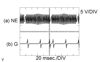
Reference: Inspection using an oscilloscope.
While idling, the correct waveform is shown in the diagram.
| ECM Terminal Name | (a) Between NE+ and NE- (b) Between G+ and G- |
| Tester Range | 5 V/DIV, 20 msec./DIV |
| Condition | Idling with warm engine |
Tech Tips
-
G stands for the camshaft position sensor signal, and NE stands for the crankshaft position sensor signal.
-
The waveform varies depending on the engine speed.
WIRING DIAGRAM
Refer to DTC P0335 Click here.
INSPECTION PROCEDURE
Note
After replacing the ECM, the new ECM needs registration Click here and initialization Click here.
Tech Tips
Read freeze frame data using an intelligent tester. Freeze frame data record the engine condition when malfunctions are detected. When troubleshooting, freeze frame data can help determine if the vehicle was moving or stationary, if the engine was warmed up or not, if the air-fuel ratio was lean or rich, and other data, from the time the malfunction occurred.
PROCEDURE
-
INSPECT CAMSHAFT POSITION SENSOR
-
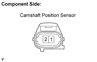
Disconnect the D10 camshaft position sensor connector.
-
Measure the camshaft position sensor resistance.
Standard resistance Tester Connection Specified Condition 1 - 2 1,850 to 2,450 Ω
at 20°C (68°F)
-
Reconnect the camshaft position sensor connector.
NG 
REPLACE CAMSHAFT POSITION SENSOR
OK 
-
-
CHECK HARNESS AND CONNECTOR (CAMSHAFT POSITION SENSOR - ECM)
-
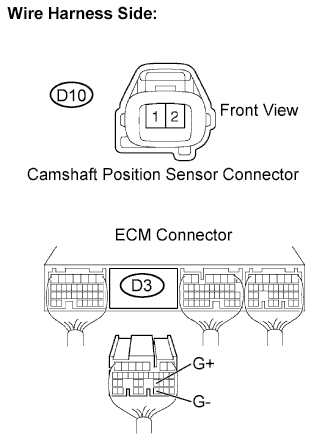
Disconnect the D10 camshaft position sensor connector.
-
Disconnect the D3 ECM connector.
-
Check the resistance.
Standard resistance (Check for open) Tester Connection Specified Condition D10-1 - G+ (D3-23) Below 1 Ω D10-2 - G- (D3-31) Below 1 Ω Standard resistance (Check for short) Tester Connection Specified Condition D10-1 or G+ (D3-23) - Body ground 10 kΩ or higher D10-2 or G- (D3-31) - Body ground 10 kΩ or higher -
Reconnect the ECM connector.
-
Reconnect the camshaft position sensor connector.
NG
REPAIR OR REPLACE HARNESS OR CONNECTOR
OK
-
-
CHECK CAMSHAFT POSITION SENSOR (SENSOR INSTALLATION)
-
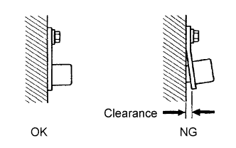
Check the sensor installation.
OK Sensor is installed correctly.
NG
SECURELY REINSTALL SENSOR
OK
-
-
CHECK PUMP DRIVE SHAFT PULLEY
-
Check the condition of the pump drive shaft pulley.
OK Pump drive shaft pulley (sensor rotor portion) does not have any cracks or deformation.
NG
REPLACE PUMP DRIVE SHAFT PULLEY
OK 
REPLACE ECM
-