ECD SYSTEM (w/o DPF), Diagnostic DTC:P0200

| DTC Code | DTC Name |
|---|---|
| P0200 | Injector Circuit / Open |
DESCRIPTION
Tech Tips
-
For more information on the injector driver (EDU) Click here.
-
If DTC P0200 is present, refer to the Diagnostic Trouble Codes (DTCs) table for common rail system Click here.
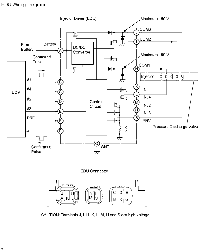
The EDU has been adopted to drive the injectors at high speed. The EDU has realized the high-speed driving under high-pressurized fuel conditions using the DC/DC converter, which provides a high-voltage and the quick-charging system. Soon after the EDU receives an injection command (IJT) signal from the ECM, the EDU responds to the command with an injector injection confirmation (IJF) signal when the current is applied to the injector.
| DTC No. | DTC Detection Condition | Trouble Area |
|---|---|---|
| P0200 |
After engine started, no injection confirmation (IJF) signal from EDU to ECM, despite ECM sending injection command (IJT) signals to EDU (1 trip detection logic) |
|
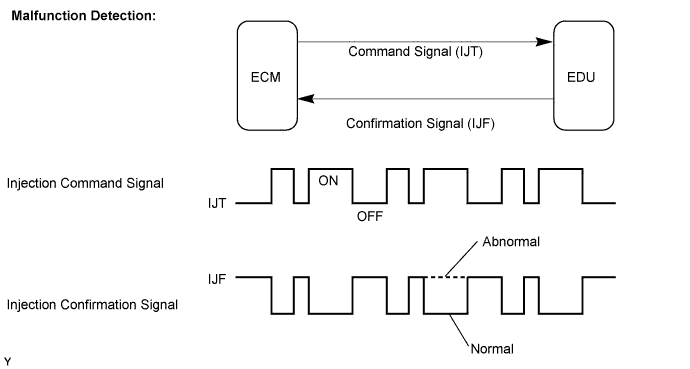
MONITOR DESCRIPTION
P0200 (Open or short in injector driver (EDU) or injector circuit):The ECM continuously monitors both injection command (IJT) signals and injection confirmation (IJF) signal. This DTC will be set if the ECM judges that the number of IJT signals and IJF signals are inconsistent.
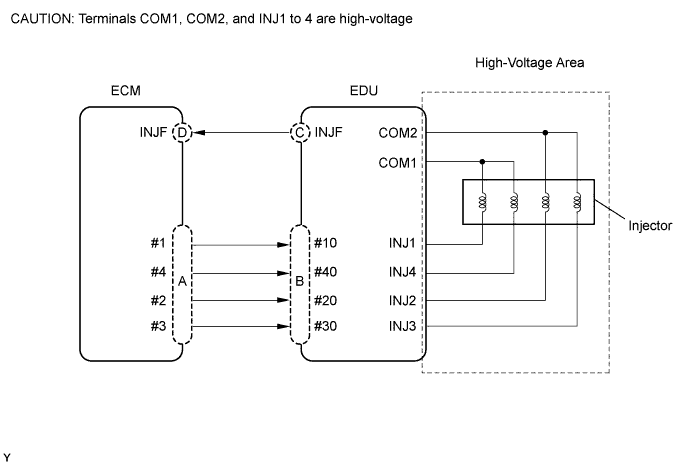
The injectors are grounded over a Field Effect Transistor (FET) and a serial resistor. This resistor creates a voltage drop, which is monitored by the EDU, in relation to the current drawn by the injector. When the injector current becomes too high, the voltage drop over the resistor becomes higher than a specified level and for that injector no IJF signal is sent to the ECM.
P0200 refers to a malfunction of injector drive circuit or injector circuit.
If this DTC is set, the ECM enters the fail-safe mode and limits engine power. The fail-safe mode continues until the ignition switch is turned OFF.
Tech Tips
Problem area can be identified by checking the waveform at the following terminals.
Tech Tips
If you check the ECM side first, inspect the following A and D in sequence. If you check the EDU side first, inspect the following B and C in sequence. This shortens inspecting time.
| Malfunction Point | Trouble Area |
|---|---|
| A |
|
| B (If A is normal) |
|
| C (If A and B are normal) |
|
| D (If A, B and C are normal) |
|
-
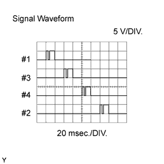
Reference: Inspection using the oscilloscope.
During idling, the correct waveform is as shown in the diagram.
ECM Terminal Name Between #1 and E1
Between #3 and E1
Between #4 and E1
Between #2 and E1
Tester Range 5 V/DIV, 20 msec./DIV Condition Idling with warm engine Inspection Point Specified Condition A and B Correct waveform as shown -
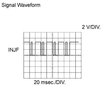
Reference: Inspection using the oscilloscope.
During idling, the correct waveform is as shown in the diagram.
ECM Terminal Name Between INJF and E1 Tester Range 2 V/DIV, 20 msec./DIV Condition Idling with warm engine Inspection Point Specified Condition C and D Correct waveform as shown
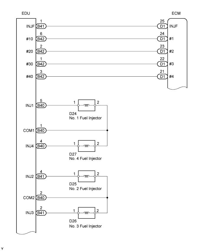
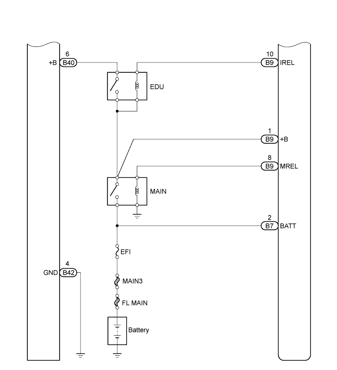
WIRING DIAGRAM
INSPECTION PROCEDURE
Note
After replacing the ECM, the new ECM needs registration Click here and initialization Click here.
Tech Tips
-
If P0200 and P1271 are present simultaneously, there is open in the INJF wire harness between the EDU and ECM, or there is open in the wire harness for both injector and pressure discharge valve.
-
Read freeze frame data using an intelligent tester. Freeze frame data record the engine condition when malfunctions are detected. When troubleshooting, freeze frame data can help determine if the vehicle was moving or stationary, if the engine was warmed up or not, if the air-fuel ratio was lean or rich, and other data, from the time the malfunction occurred.
PROCEDURE
-
CHECK ANY OTHER DTCS OUTPUT (IN ADDITION TO DTC P0200)
-
Connect an intelligent tester to the DLC3.
-
Turn the ignition switch to ON and turn the tester ON.
-
Select the following menu items: Powertrain / Engine / DTC.
-
Read DTCs.
Result Display (DTC Output) Proceed To P0200 and P1238 A P0200 B
B 
INSPECT INJECTOR Click here
A 
-
-
READ VALUE USING INTELLIGENT TESTER (COMPENSATION OF INJECTION VOLUME BETWEEN CYLINDERS)
-
Connect an intelligent tester to the DLC3.
-
Start the engine and turn the tester ON.
-
Select the following menu items: Powertrain / Engine / Data List / Injection Feedback Val #1, #2, #3 and #4.
-
Read the value.
Standard The compensatory injection volume is between -4.9 mm3/st to 4.9 mm3/st Tech Tips
-
If the injector is malfunctioning, the compensatory injection volume remains at -5.0 mm3/st to 5.0mm3/st
-
The compensatory injection volume is between -3.0 mm3/st and 3.0mm3/st
-
-
Inspect and repair the cylinder that has an improper compensation value according to the following steps.
NEXT
-
-
INSPECT INJECTOR
-
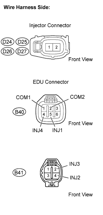
Disconnect the D24, D25, D26 and/or D27 injector connectors.
-
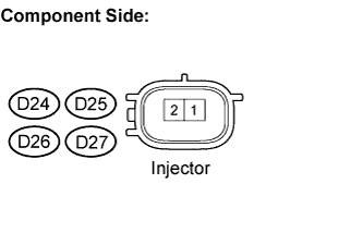
Measure the resistance between the terminals of the injection assembly.
Standard resistance Tester Connection Specified Condition 1 - 2 0.85 to 1.05 Ω
20°C (68°F)
-
Reconnect the injector connectors.
NG 
REPLACE INJECTOR
OK
-
-
CHECK HARNESS AND CONNECTOR (EDU - INJECTOR)
-
Check the harness and connector between the injector and EDU (INJ terminal).
-
Disconnect the D24, D25, D26 and/or D27 injector connectors.
-
Disconnect the B40 and/or B41 EDU connectors.
-
Check the resistance.
Standard resistance (Check for open) Tester Connection Specified Condition D24-1 - INJ1 (B40-5) Below 1 Ω D25-1 - INJ2 (B41-4) D26-1 - INJ3 (B41-2) D27-1 - INJ4 (B40-4) D24-2 - COM1 (B40-1) D25-2 - COM2 (B40-2) D26-2 - COM2 (B40-2) D27-2 - COM1 (B40-1) Standard resistance (Check for short) Tester Connection Specified Condition D24-1 or INJ1 (B40-5) - Body ground 10 kΩ or higher D25-1 or INJ2 (B41-4) - Body ground D26-1 or INJ3 (B41-2) - Body ground D27-1 or INJ4 (B40-4) - Body ground D24-2 or COM1 (B40-1) - Body ground D25-2 or COM2 (B40-2) - Body ground D26-2 or COM2 (B40-2) - Body ground D27-2 or COM1 (B40-1) - Body ground -
Reconnect the EDU connector.
-
Reconnect the injector connectors.
-
NG
REPAIR OR REPLACE HARNESS OR CONNECTOR
OK
-
-
CHECK HARNESS AND CONNECTOR (EDU - ECM)
-
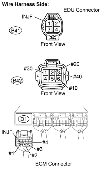
Disconnect the B41 and B42 EDU connectors.
-
Disconnect the D1 ECM connector.
-
Check the resistance.
Standard resistance (Check for open) Tester Connection Specified Condition #10 (B42-6) - #1 (D1-24) Below 1 Ω #20 (B42-2) - #2 (D1-23) #30 (B42-1) - #3 (D1-22) #40 (B42-3) - #4 (D1-21) IJNF (B41-1) - INJF (D1-25) Standard resistance (Check for short) Tester Connection Specified Condition #10 (B42-6) or #1 (D1-24) - Body ground 10 kΩ or higher #20 (B42-2) or #2 (D1-23) - Body ground #30 (B42-1) or #3 (D1-22) - Body ground #40 (B42-3) or #4 (D1-21) - Body ground IJNF (B41-1) or INJF (D1-25) - Body ground -
Reconnect the ECM connector.
-
Reconnect the EDU connectors.
NG
REPAIR OR REPLACE HARNESS OR CONNECTOR
OK
-
-
INSPECT INJECTOR DRIVER (EDU) (BATTERY VOLTAGE)
-
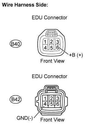
Disconnect the B40 and B42 EDU connectors.
-
Turn the ignition switch to ON.
-
Measure the voltage between the terminals of the EDU connectors.
Standard voltage Tester Connection Specified Condition +B (B40-6) - GND (B42-4) 11 to 14 V -
Reconnect the EDU connectors.
NG
CHECK INJECTOR DRIVER POWER SOURCE CIRCUIT (BATTERY - EDU)
OK
-
-
REPLACE INJECTOR DRIVER (EDU)
Replace injector driver Click here.
NEXT
-
CHECK WHETHER DTC OUTPUT RECURS
-
Connect an intelligent tester to the DLC3.
-
Turn the ignition switch to ON and turn the tester ON.
-
Select the following menu items: Powertrain / Engine / DTC / Clear.
-
Clear DTCs.
-
Start the engine.
-
Allow the engine to idle for 30 seconds or more.
-
Select the following menu items: Powertrain / Engine / DTC.
-
Read DTCs.
Result Display (DTC Output) Proceed To No output A P0200 B Tech Tips
If the engine does not stat, replace the ECM.
B
REPLACE ECM
A 
END
-