ECD SYSTEM (w/o DPF), Diagnostic DTC:P0100, P0102, P0103

| DTC Code | DTC Name |
|---|---|
| P0100 | Mass or Volume Air Flow Circuit |
| P0102 | Air Flow Meter Circuit Low Input |
| P0103 | Air Flow Meter Circuit High Input |
DESCRIPTION
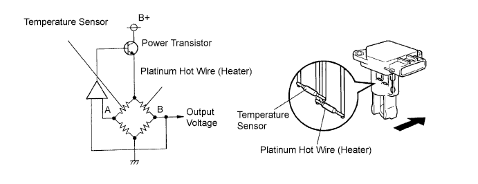
The mass air flow meter uses a platinum hot wire. The mass air flow meter consists of a platinum hot wire, a temperature sensor and a control circuit installed in a plastic housing. The mass air flow meter works on the principle that the hot wire and temperature sensor located in the intake air by-pass of the housing detect any changes in the intake air temperature.
The hot wire is maintained at the predetermined temperature by controlling the current flow through the hot wire. This current flow is then related as the output voltage of the mass air flow meter.
The circuit is constructed so that the platinum hot wire and temperature sensor provide a bridge circuit, with the power transistor controlled so that the potential of A and B remains equal to maintain the predetermined temperature.
| DTC No. | DTC Detection Condition | Trouble Area |
|---|---|---|
| P0100 | Open or short in mass air flow meter circuit for more than 3 seconds with engine speed at 2,000 rpm or less (1 trip detection logic) |
|
| P0102 | Open in mass air flow meter circuit for more than 3 seconds with engine speed at 2,000 rpm or less (1 trip detection logic) |
|
| P0103 | Short in mass air flow meter circuit for more than 3 seconds with engine speed at 2,000 rpm or less (1 trip detection logic) |
|
Tech Tips
After confirming DTC P0100, P0102 or P0103, check the mass air flow ratio by selecting the following menu items on an intelligent tester: Powertrain / Engine / Data List / MAF.
| Reference | ||||||
|---|---|---|---|---|---|---|
|
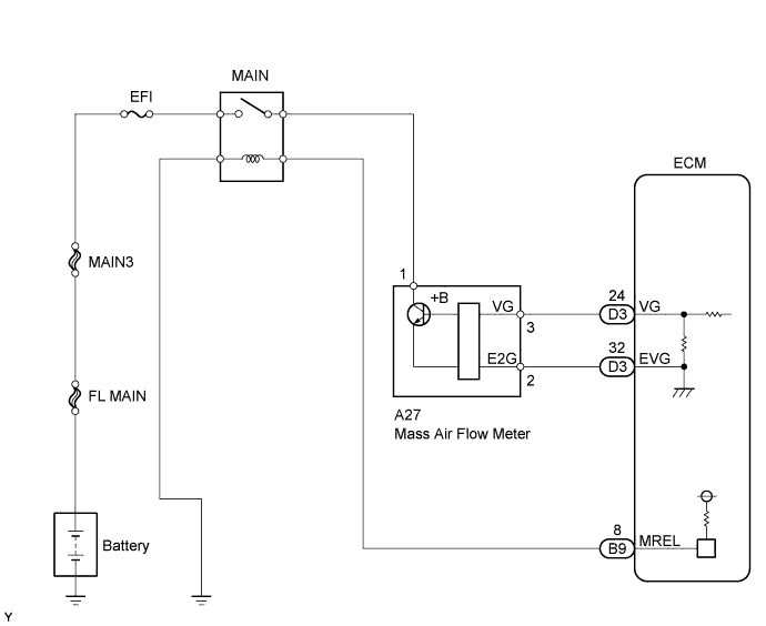
WIRING DIAGRAM
INSPECTION PROCEDURE
Note
After replacing the ECM, the new ECM needs registration Click here and initialization Click here.
Tech Tips
Read freeze frame data using an intelligent tester. Freeze frame data record the engine condition when malfunctions are detected. When troubleshooting, freeze frame data can help determine if the vehicle was moving or stationary, if the engine was warmed up or not, if the air-fuel ratio was lean or rich, and other data, from the time the malfunction occurred.
PROCEDURE
-
READ VALUE USING INTELLIGENT TESTER (MAF)
-
Connect an intelligent tester to the DLC3.
-
Start the engine and turn the tester ON.
-
Select the following menu items: Powertrain / Engine / Data List / MAF.
-
Read the value.
Result Air Flow Rate (g/sec) Proceed To 0.0 A 174.0 or more B Between 1 and 173.0 (*1) C *1: The value should change in accordance with engine speed.
B 
INSPECT ECM (SENSOR GROUND) Click here
C 
CHECK FOR INTERMITTENT PROBLEMS
A 
-
-
INSPECT MASS AIR FLOW METER (POWER SOURCE CIRCUIT)
-
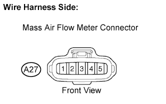
Disconnect the A27 mass air flow meter connector.
-
Turn the ignition switch to ON.
-
Measure the voltage of the wire harness side connector and the body ground.
Standard voltage Tester Connection Specified Condition +B (A27-1) - Body ground 11 to 14 V -
Reconnect the mass air flow meter connector.
NG
CHECK HARNESS AND CONNECTOR (MASS AIR FLOW METER - MAIN RELAY) Click here
OK
-
-
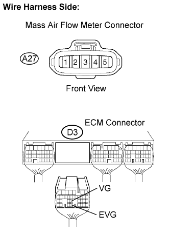
INSPECT ECM (VG VOLTAGE)
-
Start the engine.
-
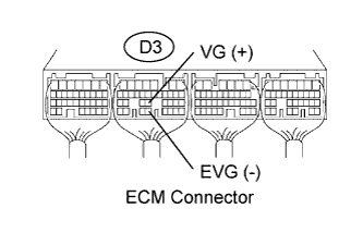
Measure the voltage of the ECM connector.
Tech Tips
The A/C switch should be turned OFF.
Standard voltage Tester Connection Condition Specified Condition VG (D3-24) - EVG (D3-32) Engine idling 0.2 to 3.1 V
OK
REPLACE ECM
NG
-
-
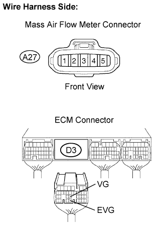
CHECK HARNESS AND CONNECTOR (MASS AIR FLOW METER - ECM)
-
Disconnect the A27 mass air flow meter connector.
-
Disconnect the D3 ECM connector.
-
Check the resistance.
Standard resistance (Check for open) Tester Connection Specified Condition VG (A27-3) - VG (D3-24) Below 1 Ω E2G (A27-2) - EVG (D3-32) Below 1 Ω Standard resistance (Check for short) Tester Connection Specified Condition VG (A27-3) or VG (D3-24) - Body ground 10 kΩ or higher -
Reconnect the mass air flow meter connector.
-
Reconnect the ECM connector.
NG
REPAIR OR REPLACE HARNESS OR CONNECTOR
OK 
REPLACE MASS AIR FLOW METER
-
-
CHECK HARNESS AND CONNECTOR (MASS AIR FLOW METER - MAIN RELAY)
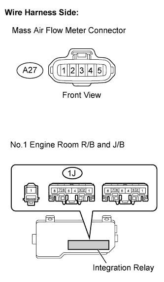
-
Disconnect the A27 MAF meter connector.
-
Remove the integration relay (MAIN relay) from the No.1 engine room R/B and J/B.
-
Check the resistance.
Standard resistance (Check for open) Tester Connection Specified Condition +B (A27-1) - Integration relay (1J-4) Below 1 Ω Standard resistance (Check for short) Tester Connection Specified Condition +B (A27-1) or Integration relay (1J-4) - Body ground 10 kΩ or higher -
Reconnect the MAF meter connector.
-
Reinstall the integration relay.
NG
REPAIR OR REPLACE HARNESS OR CONNECTOR
OK
CHECK ECM POWER SOURCE CIRCUIT
-
-
INSPECT ECM (SENSOR GROUND)
-
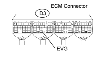
Measure the resistance of the ECM connector and body ground.
Standard resistance Tester Connection Specified Condition EVG (D3-32) - Body ground Below 1 Ω
NG
REPLACE ECM
OK
-
-
CHECK HARNESS AND CONNECTOR (MASS AIR FLOW METER - ECM)
-
Disconnect the A27 mass air flow meter connector.
-
Disconnect the D3 ECM connector.
-
Check the resistance.
Standard resistance (Check for open) Tester Connection Specified Condition VG (A27-3) - VG (D3-24) Below 1 Ω E2G (A27-2) - EVG (D3-32) Below 1 Ω Standard resistance (Check for short) Tester Connection Specified Condition VG (A27-3) or VG (D3-24) - Body ground 10 kΩ or higher -
Reconnect the mass air flow meter connector.
-
Reconnect the ECM connector.
NG
REPAIR OR REPLACE HARNESS OR CONNECTOR
OK
REPLACE MASS AIR FLOW METER
-