COMMON RAIL (w/o DPF) INSTALLATION

-
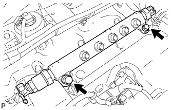
INSTALL COMMON RAIL ASSEMBLY
-
Install the common rail with the 2 bolts.
- Torque:
- 38 N*m { 387 kgf*cm, 28 ft.*lbf }
-
Connect the fuel hose.
-
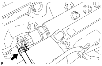
Connect the 2 connectors to the common rail.
-
-
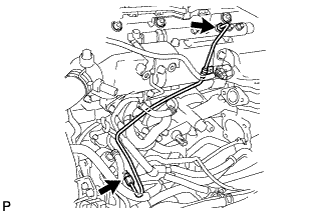
INSTALL FUEL INLET PIPE SUB-ASSEMBLY
Note
-
When replacing the fuel supply pump, common rail, cylinder block, cylinder head, cylinder head gasket, or timing gear case with a new one, replace the fuel inlet pipe.
-
Be careful not to adhere dusts, dirt or any other materials onto the joint area of the fuel inlet pipe.
-
Temporarily install the fuel inlet pipe.
-
Connect the No. 1 injection pipe clamp with the bolt.
- Torque:
- 5.0 N*m { 51 kgf*cm, 44 in.*lbf }
-
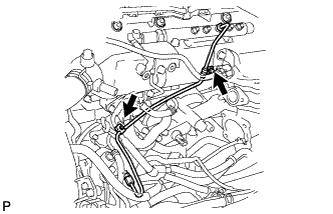
Install the No. 2 injection pipe clamp with the bolt.
- Torque:
- 5.0 N*m { 51 kgf*cm, 44 in.*lbf }
-
Using SST, tighten the union nut on the common rail side.
- SST
- 09023-12701
- Torque:
- 32 N*m { 326 kgf*cm, 24 ft.*lbf, for use with SST }
- 35 N*m { 357 kgf*cm, 26 ft.*lbf, for use without SST }
Tech Tips
-
Use a torque wrench with a fulcrum length of 300 mm (11.81 in.).
-
This torque value is effective when SST is parallel to a torque wrench.
-
Using SST, tighten the union nut on the supply pump side.
- SST
- 09023-12701
- Torque:
- 32 N*m { 326 kgf*cm, 24 ft.*lbf, for use with SST }
- 35 N*m { 357 kgf*cm, 26 ft.*lbf, for use without SST }
Tech Tips
-
Use a torque wrench with a fulcrum length of 300 mm (11.81 in.).
-
This torque value is effective when SST is parallel to a torque wrench.
-
-
INSTALL OIL LEVEL GAUGE GUIDE
-
INSTALL INJECTION PIPE
Note
-
When replacing the fuel injector, common rail, or cylinder head with a new one, replace injection pipes No. 1, No. 2, No. 3, and No. 4.
-
Keep the injection pipe connection clean.
-
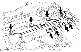
Install the injection pipes.
-
Temporarily install the 4 injection pipes.
-
Install the 2 No. 2 injection pipe clamps with the 2 bolts.
- Torque:
- 5.0 N*m { 51 kgf*cm, 44 in.*lbf }
-
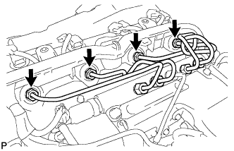
Using SST, tighten the union nut on the fuel injector side to the specified torque.
- SST
- 09023-12701
- Torque:
- 32 N*m { 326 kgf*cm, 24 ft.*lbf, for use with SST }
- 35 N*m { 357 kgf*cm, 26 ft.*lbf, for use without SST }
Tech Tips
-
Use a torque wrench with a fulcrum length of 300 mm (11.81 in.).
-
This torque value is effective when SST is parallel to a torque wrench.
-
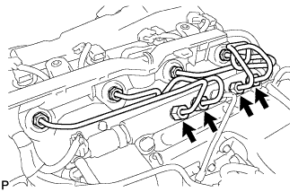
Using SST, tighten the union nut on the common rail side to the specified torque.
- SST
- 09023-12701
- Torque:
- 32 N*m { 326 kgf*cm, 24 ft.*lbf, for use with SST }
- 35 N*m { 357 kgf*cm, 26 ft.*lbf, for use without SST }
Tech Tips
-
Use a torque wrench with a fulcrum length of 300 mm (11.81 in.).
-
This torque value is effective when SST is parallel to a torque wrench.
-
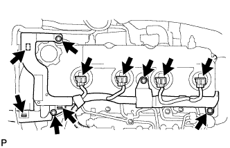
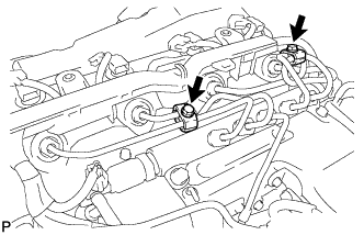
Install the 3 bolts.
-
Connect the fuel injector connector and harness clamps.
-
-
-
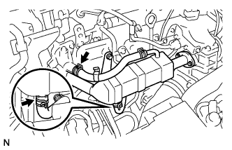
INSTALL NO. 4 AIR HOSE
-
Install the No. 4 air hose with the 2 clamps.
- Torque:
- 6.0 N*m { 61 kgf*cm, 53 in.*lbf }
-
-
TEMPORARILY TIGHTEN EGR COOLER ASSEMBLY

-
Temporarily tighten the EGR cooler assembly.
-
Temporarily tighten the EGR cooler assembly and new gaskets.
-
Temporarily tighten the EGR cooler assembly stay bolt.
-
Tighten the EGR cooler assembly with the 2 nuts and 2 bolts.
- Torque:
- 13 N*m { 133 kgf*cm, 10 ft.*lbf }
-
-
-
TIGHTEN EGR COOLER ASSEMBLY
-
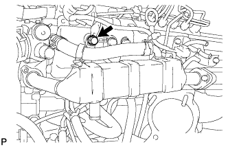
Tighten the EGR cooler assembly stay bolt.
- Torque:
- 22 N*m { 224 kgf*cm, 16 ft.*lbf }
-
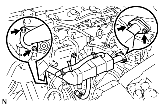
Install the No. 2 water by-pass hose with the clip.
-
Install the No. 4 water by-pass hose with the clip.
-
-
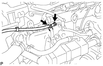
CONNECT OIL RETURN HOSE
-
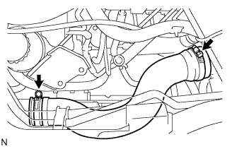
Connect the oil return hose with the 2 clips.
-
-
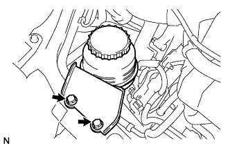
INSTALL VANE PUMP OIL RESERVOIR ASSEMBLY
-
Install the vane pump oil reservoir assembly with the 2 bolts.
- Torque:
- 8.0 N*m { 82 kgf*cm, 71 in.*lbf }
-
-
INSTALL ENGINE SERVICE HOLE SUB COVER SUB-ASSEMBLY
-
Install the engine service hole sub cover sub-assembly with the 5 bolts.
- Torque:
- 13 N*m { 133 kgf*cm, 10 ft.*lbf }
-
-
INSTALL FRONT DOOR SCUFF PLATE RH
-
INSTALL FRONT SEAT ASSEMBLY RH
-

Connect the front seat inner belt assembly connector and install the front seat assembly.
-
Align the front seat assembly adjuster pin with the holes in the body.
-
Move the front seat assembly to the rearmost position.
Note
Make sure that the front seat assembly is securely locked.
-
Temporarily tighten the 2 bolts on the front side of the front seat assembly.
-
Move the front seat assembly fully forward.
Note
Make sure that the front seat assembly is securely locked.
-
Temporarily tighten the 2 bolts on the rear side of the front seat assembly.
-
Move the front seat assembly to the rearmost position.
Note
Make sure that the front seat assembly is securely locked.
-
Fully tighten the 2 bolts on the front side of the front seat assembly in the order of outer and inner side.
- Torque:
- 39 N*m { 398 kgf*cm, 29 ft.*lbf }
-
Move the front seat assembly fully forward.
Note
Make sure that the front seat assembly is securely locked.
-
Fully tighten the 2 bolts on the rear side of the front seat assembly in the order of outer and inner side.
- Torque:
- 39 N*m { 398 kgf*cm, 29 ft.*lbf }
-
-
CONNECT CABLE TO NEGATIVE BATTERY TERMINAL
- Torque:
- 5.4 N*m { 55 kgf*cm, 48 in.*lbf }
-
ADD ENGINE COOLANT
-
Firmly tighten the drain plugs.
-
Fill the radiator reserve tank assembly with coolant to the top of the inlet.
Coolant capacity Condition Capacity w/ rear heater 18.2 liters (19.2 US qts, 16.0 lmp. qts) w/o rear heater 16.2 liters (17.0 US qts, 14.0 lmp. qts) Note
Do not substitute plain water for engine coolant.
Tech Tips
-
Use of improper coolants may damage the engine cooling system.
-
Use only Toyota Super Long Life Coolant or similar high quality ethylene glycol based non-silicate, non-amine, non-nitrite, and non-borate coolant with long-life hybrid organic acid technology (coolant with long-life hybrid organic acid technology consists of a combination of low phosphates and organic acids).
-
-
Loosen the bleeder plug of the outlet housing.
-
When air is bled and the coolant drains out, firmly install the bleeder plug.
-

Add coolant up to the B line mark in the radiator reserve tank assembly and install the radiator cap.
-
Warm up the engine until the thermostat opens.
-
While the thermostat is open, circulate the coolant for several minutes.
Tech Tips
The thermostat open timing can be confirmed by pressing the inlet radiator hose by hand, and checking when the engine coolant starts to flow inside the hose.
-
-

After the engine cools down, check that the coolant level is between the LOW and FULL level marks.
-
-
INSPECT FOR ENGINE COOLANT LEAK
-
BLEED FUEL LINE
-
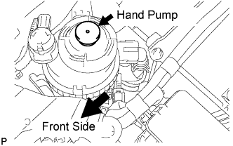
Using a hand pump, bleed air from the fuel system until pumping becomes difficult.
-
-
INSPECT FOR FUEL LEAK
-
Perform the Active Test.
-
Connect the intelligent tester to the DLC3.
-
Turn the ignition switch ON.
-
Turn the intelligent tester ON.
-
Select the following menu items: Powertrain / ECD / Active Test.
-
Perform the Active Test.
Intelligent Tester Display Test Details Control Range Diagnostic Notes Test the Fuel Leak Pressurizes common rail internal fuel pressure, and checks for fuel leaks Stop/Start
-
Fuel pressure inside common rail pressurized to specified value and engine speed increased to 2,000 rpm when ON is selected
-
Above conditions preserved while test is ON
-
-
-
-
INSPECT FOR OIL LEAK
-
INSPECT FOR EXHAUST GAS LEAK
-
PERFORM INITIALIZATION
-
Perform initialization procedures Click here.
Note
Certain systems need to be initialized after reconnecting the cable to the negative (-) battery terminal.
-