FUEL INJECTOR INSTALLATION

-
INSTALL INJECTOR ASSEMBLY
-
Install 4 new nozzle seats to the cylinder head.
-
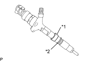
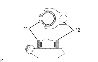
Text in Illustration *1 New Back-Up Ring *2 New O-ring Install a new back-up ring and O-ring to each injector.
-
Apply a light coat of oil onto the O-ring to each injector.
-
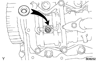
Install the injector to the cylinder head.
Note
-
At this time, insert the injector until it touches the nozzle sheet surface.
-
If the injector comes to float up with reaction of O-ring when installing the injector to the cylinder head, pull out the injector once and then install it again.
-
After the head cover is equipped, install an irregular object prevention cover temporarily until the injection pipe is installed.
-
Each injector cylinder should be installed to its original position.
-
-
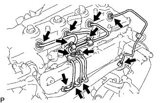
Temporarily install the 4 injection pipes.
Tech Tips
For positioning the injector, temporarily install the injection pipe.
-
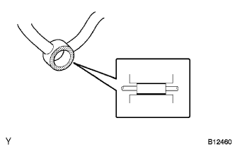
Before installing the nozzle leakage pipe using the straight edge check that there is no scratch and deformation (dent) on the seal surface of the unions (at five positions).
If scratch or deformation exists, change it to a new one.
-
Place the leakage pipe and 5 new gaskets.
-
Apply a light coat of oil onto 4 hollow screws and union bolt.
-
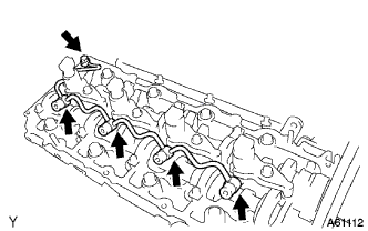
Tighten the 4 hollow screws and union bolt by hand.
-
-
INSTALL CYLINDER HEAD COVER SUB-ASSEMBLY
-
INSTALL NOZZLE HOLDER CLAMP
-
Set the spring to each injector as shown in the illustration.
Text in Illustration *1 Spring *2 Nozzle Holder Clamp -
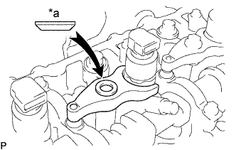
Text in Illustration *a Upward Set the washer on the nozzle holder clamp as shown in the illustration.
-
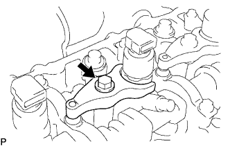
Tighten the bolt.
Tech Tips
Apply a light coat of engine oil on the threads and under the heads of the nozzle holder clamp bolts.
- Torque:
- 21.6 N*m { 220 kgf*cm, 16 ft.*lbf }
Note
-
Clip the injector at the fork portion with a clamp which is set on the head of the cam cap bolt. At this time, check that the clamp does not hold the injector where the spring is attached.
-
To torque the clamp bolt, temporarily torque it with hand until the bearing surface of the bolt touches the washer, and then tighten it by the specified torque.
-
When tightening it by the specified torque, pay attention not to tilt the bolt and the clamp.
-
Tighten the 4 hollow screws and union bolt.
- Torque:
- Hollow screw
- 16 N*m { 163 kgf*cm, 12 ft.*lbf }
- Union bolt
- 12.5 N*m { 128 kgf*cm, 9 ft.*lbf }
-
-
INSTALL NOZZLE LEAKAGE PIPE ASSEMBLY
Note
In case of over-torque, the nozzle leakage pipe can not be reused, and therefore change it to a new one.
-
Remove the 4 injection pipes.
-
Check that there are no leaks from the connection of nozzle leakage pipe.
-
Remove the 2 bolts, union bolt, check valve, No. 2 nozzle leakage pipe and 2 gaskets.
-
Purchase a new check valve.
Part No. 23769-30010
-
-
Install the No. 2 nozzle leakage pipe and gasket with the check valve to the cylinder head.
- Torque:
- 16 N*m { 163 kgf*cm, 12 ft.*lbf }
-
Apply a light coat of soapy water (any fluid to detect fuel leakage) on the nozzle leakage pipe connection.
-
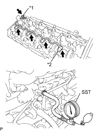
Text in Illustration *1 Union Bolt *2 Hollow Screw Using SST (turbo charger pressure gauge), apply the SST to the fuel return side of the No. 2 nozzle leakage pipe, and maintain 250 kPa (1.0 kgf*cm2, 14.5 psi) of pressure for 60 seconds to check that there are no bubbles from applying the soapy water place.
- SST
- 09992-00242
-
When checking the leakage, be sure to remove the ball and spring in the check valve before the operation.
-
After the leak check, wipe off soapy water from the connection of nozzle leakage pipe.
-
Remove SST, check valve, No. 2 nozzle leakage pipe and gasket.
-
Temporarily install the No. 2 nozzle leakage pipe and 2 new gaskets with the 2 bolts, union bolt and check valve.
Tech Tips
Never reinstall the disassembled check valve on the engine.
-
-
INSTALL CYLINDER HEAD COVER SUB-ASSEMBLY
-
INSTALL NOZZLE HOLDER SEAL
-
INSTALL INJECTION PIPE SET
-
Temporarily install the 4 injection pipes.
-
Install the injection pipe No. 1 clamp with the bolt.
- Torque:
- 5.0 N*m { 51 kgf*cm, 44 in.*lbf }
Note
-
Make sure that the rubber is fit inside the clamp.
-
When installing, properly position the rubber and clamp.
-
Install the injection pipe clamp No. 2 with the bolt.
- Torque:
- 5.0 N*m { 51 kgf*cm, 44 in.*lbf }
-
Install the injection pipe clamp No. 3 with the 2 nuts.
- Torque:
- 5.0 N*m { 51 kgf*cm, 44 in.*lbf }
-
Using a 17 mm union nut wrench, tighten the injection pipe union of common rail side.
- Torque:
- 35 N*m { 357 kgf*cm, 26 ft.*lbf }
Note
Use the formula to calculate special torque values for situations where a union nut wrench is combined with a torque wrench Click here
-
Using a 17 mm union nut wrench, tighten the injection pipe union of injector side.
- Torque:
- 35 N*m { 357 kgf*cm, 26 ft.*lbf }
Note
Use the formula to calculate special torque values for situations where a union nut wrench is combined with a torque wrench Click here
-
Tighten the 2 bolts, union bolt and check valve for No. 2 nozzle leakage pipe.
- Torque:
- Bolt
- 12.7 N*m { 130 kgf*cm, 9 ft.*lbf }
- Union bolt
- 12.5 N*m { 128 kgf*cm, 9 ft.*lbf }
- Check valve
- 16 N*m { 163 kgf*cm, 12 ft.*lbf }
-
-
BLEED INJECTION PIPE
-
Move the priming pump of the fuel filter up and down until it becomes hard.
-
-
INSTALL ENGINE WIRE
-
INSTALL VSV ASSEMBLY
-
INSTALL ENGINE SERVICE HOLE SUB COVER SUB-ASSEMBLY (W/O TILT CAB CAB TYPE)
-
Install the front door scuff.
-
Install the floor mat.
-
Install the engine service hole sub-cover with the 7 bolts.
-
-
INSTALL PARKING BRAKE SHOE LEVER SUB-ASSEMBLY (W/O TILT CAB CAB TYPE)
-
INSTALL TRANSMISSION FLOOR SHIFT ASSEMBLY (W/O TILT CAB CAB TYPE)
-
INSTALL FLOOR SHIFT CABLE TRANSMISSION CONTROL SHIFT
-
Install the clip and nut, and then connect the shift cable to the transmission.
-
-
INSTALL FLOOR SHIFT CABLE TRANSMISSION CONTROL SELECT
-
Install the clip and nut, and then connect the select cable to the transmission.
-
-
INSTALL FRONT SEAT ASSEMBLY (DRIVER SEAT) (W/O TILT CAB CAB TYPE)
-
INSTALL FRONT SEAT ASSEMBLY RH (W/O TILT CAB CAB TYPE)
-
INSTALL BATTERY NEGATIVE TERMINAL
-
INSPECT FUEL LEAK
CAUTION:
-
During ACTIVE TEST mode, engine speed goes high and combustion noise becomes loud, so pay attention.
-
During ACTIVE TEST mode, fuel becomes high pressure, so take much care not to expose your eyes, hands, or body to the fuel.
-
Check that there are no leaks from any part of the fuel system when the engine stops.
If there is fuel leakage, replace those parts.
-
While cranking or starting the engine, check that there are no leaks from any part of the fuel system.
If there is fuel leakage, replace those parts.
-
Disconnect the return hose from the common rail.
-
While cranking the engine, check fuel leakage from the return pipe.
If there is fuel leakage, replace the common rail assembly Click here.
-
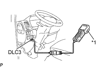
Text in Illustration *1 Intelligent Tester Connect the intelligent tester to the DLC3.
-
Start the engine and push the intelligent tester main switch ON.
-
Select the FUEL LEAK test of ACTIVE TEST mode on the intelligent tester.
-
If you have no intelligent tester, depress the accelerator pedal quickly and fully to increase the engine speed at maximum and keep it for 2 seconds. Repeat this operation several times.
-
Check that there are no leaks from any part of the fuel system.
Note
If the leakage from the return pipe is less than 10 cc (0.6 cu in.) in a minute, it is acceptable.
If there is fuel leakage, replace those parts.
-
Reconnect the return hose to the common rail.
-