ENGINE UNIT REMOVAL

-
REMOVE ENGINE ASSEMBLY
-
REMOVE ENGINE WIRE
-
REMOVE TIMING BELT
-
REMOVE PUMP DRIVE SHAFT PULLEY
-
REMOVE VACUUM PUMP ASSEMBLY
-
Remove the 2 nuts and vacuum pump.
-
Remove 2 the O-rings.
-
-
REMOVE CRANKSHAFT PULLEY
-
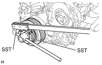
Using SST, remove the pulley bolt and plate.
- SST
- 09213-58012
- 09330-00021
-
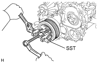
Using SST, remove the crankshaft pulley.
- SST
- 09950-50013 ( 09951-05010, 09952-05010, 09953-05010, 09954-05021 )
-
-
REMOVE EGR PIPE SUB-ASSEMBLY NO.1
-
Remove the 2 nuts.
-
Remove the EGR control valve, EGR pipe sub-assembly and 2 gaskets.
-
-
REMOVE VSV ASSEMBLY
-
Remove the 2 bolts and VSV assembly.
-
-
REMOVE OIL FILTER SUB-ASSEMBLY
-
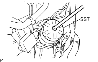
Using SST, remove the oil filter.
- SST
- 09228-10002
Tech Tips
As the oil in the filter flows out through the drain hose, place the drain oil container under the drain hose.
-
Clean the oil filter contact surface on the oil filter mounting.
-
Lubricate the filter rubber gasket with clean engine oil.
-
-
REMOVE INJECTION PIPE SET
-
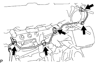
Remove the 2 nuts and injection pipe clamp No. 3.
-
Remove the bolt and injection pipe clamp No. 2.
-
Remove the bolt and injection pipe clamp No. 1.
-
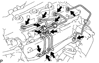
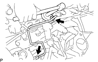
Using a 17 mm union nut wrench, loosen the injection pipe unions of common rail side.
-
Using a 17 mm union nut wrench, loosen the injection pipe unions of injector side.
Note
-
After removing the fuel pipe, affix the gum tape to the common rail for preventing dust.
-
After removing the fuel pipe, put a vinyl bag and rubber band to prevent mixing foreign objects over the injectors inlet.
-
-
-
REMOVE FUEL INLET PIPE SUB-ASSEMBLY
-
Remove the bolt and injection pipe clamp No. 2.
-
Using a union wrench 17mm, loosen the fuel inlet union of common rail side.
-
Using a union wrench 17 mm, loosen the fuel inlet pipe union of pump side.
-
Remove the inlet pipe sub-assembly.
Note
After removing the fuel pipe, affix the gum tape to the pump, common rail, and the whole injector installation area of the cylinder head cover for preventing dust.
-
-
REMOVE NOZZLE LEAKAGE PIPE ASSEMBLY NO.2
-
Disconnect the fuel hose from the nozzle leakage pipe assembly No. 2.
-
Remove the 2 bolts, 2 union bolts, check valve, nozzle leakage pipe assembly No. 2 and 3 gaskets.
-
-
REMOVE INTAKE MANIFOLD
-
Remove the 4 bolts, 2 nuts, intake manifold and gasket.
-
-
REMOVE TURBO WATER HOSE NO.1
-
REMOVE WATER OUTLET
-
REMOVE GLOW PLUG ASSEMBLY
-
REMOVE COMMON RAIL ASSEMBLY
-
REMOVE INJECTION PUMP ASSEMBLY
-
REMOVE OIL COOLER COVER SUB-ASSEMBLY
-
Disconnect the oil pressure switch connector.
-
Disconnect the engine coolant temperature sensor connector.
-
Remove the 2 nuts and disconnect the vacuum pipe.
-
Remove the 13 bolts, oil cooler cover sub-assembly and gasket.
-
-
REMOVE VACUUM PIPE
-
REMOVE VENTILATION HOSE HEAT INSULATOR
-
REMOVE EXHAUST MANIFOLD
-
Remove the 6 bolts, 2 nuts, exhaust manifold and gasket.
-
-
REMOVE WATER BY-PASS PIPE SUB-ASSEMBLY NO.2
-
REMOVE WATER INLET
-
REMOVE OIL LEVEL GAGE GUIDE
-
Remove the bolt and level gauge with guide assembly.
-
-
REMOVE V-RIBBED BELT TENSIONER ASSEMBLY
-
Remove the 6 bolts and alternator with belt tensioner assembly.
-
-
REMOVE CRANK POSITION SENSOR
-
REMOVE CRANK POSITION NO.2 SENSOR
-
REMOVE WATER TEMPERATURE SENDER GAGE ASSEMBLY
-
REMOVE ENGINE OIL LEVEL SENSOR
-
REMOVE ENGINE MOUNTING BRACKET FRONT NO.1 LH
-
REMOVE ENGINE MOUNTING BRACKET FRONT NO.1 RH