CYLINDER HEAD GASKET INSTALLATION

-
CLEAN CYLINDER BLOCK
-
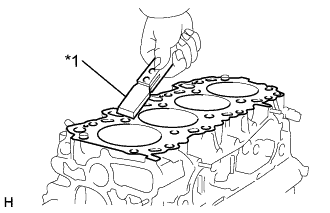
Text in Illustration *1 Gasket Scraper Turn the crankshaft, and bring each piston to the top dead center (TDC). Using a gasket scraper, remove all the carbon from the piston top surface.
-
Remove all the gasket material from the top of the cylinder block.
Note
Be careful not to scratch the surfaces.
-
Using compressed air, blow carbon and oil from the bolt holes.
CAUTION:
Protect your eyes when using high-compressed air.
-
-
CLEAN CYLINDER HEAD SUB-ASSEMBLY
-
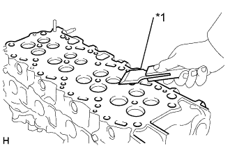
Text in Illustration *1 Gasket Scraper Using a gasket scraper, remove all the gasket material from the cylinder block contact surface.
Note
Be careful not to scratch the cylinder block contact surface.
-
-
INSTALL SEMICIRCULAR PLUG
-
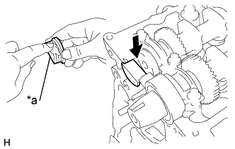
Text in Illustration *a Seal Packing Remove any old packing (FIPG) material.
-
Apply seal packing to the semi circular plug as shown.
Seal packing Toyota Genuine Seal Packing Black, Three Bond 1207B or equivalent Thickness 0.5 mm (0.020 in.) -
Install the semi circular plug to the cylinder head.
Note
Prevent FIPG from being stuck to the camshaft thrust groove.
-
-
INSTALL CYLINDER HEAD GASKET
-
Check the piston protrusions for each cylinder.
-
Clean the cylinder block with solvent.
-
Set the piston of the cylinder to be measured to slightly before TDC.
-
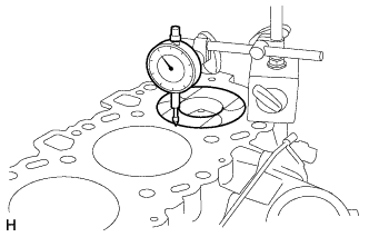
Place a dial indicator on the cylinder block, and set the dial indicator at 0 mm (0 in.).
Tech Tips
-
Use a dial indicator measuring tip as shown in the illustration.
-
Make sure that the measuring tip is square to the cylinder block gasket surface and piston head when taking the measurements.
-
-
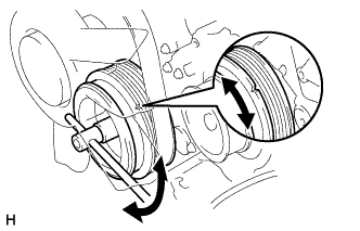
Find where the piston head protrudes most by slowly turning the crankshaft clockwise and counterclockwise.
-
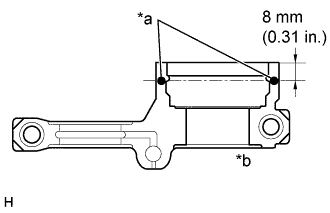
Measure each cylinder at 2 places as shown in the illustration, making a total of 8 measurements.
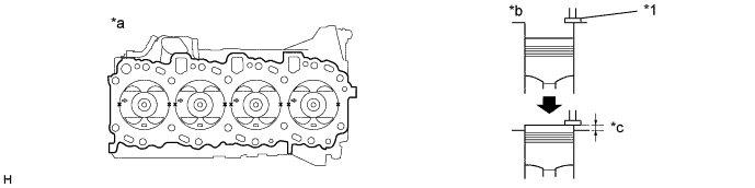
Text in Illustration *1 Measuring Tip - - *a Front *b X Measuring Point *c Protrusion - - -
For the piston protrusion value of each cylinder, use the average of the 2 measurements of each cylinder.
Tech Tips
When removing piston and connecting rod assembly: If the protrusion is not as specified, remove the piston and connecting rod assembly and reinstall it.
-
-
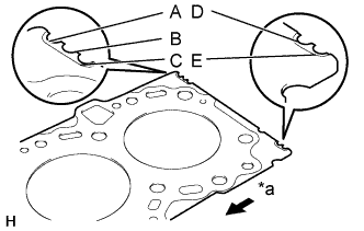
Text in Illustration *a Front Select a new cylinder head gasket.
Tech Tips
There are 5 sizes of new cylinder head gaskets, marked "A", "B", "C", "D" or "E" according.
Installed cylinder head gasket thickness A 0.80 - 0.90 mm (0.0315 - 0.0354 in.) B 0.85 - 0.95 mm (0.0335 - 0.0374 in.) C 0.90 - 1.00 mm (0.0354 - 0.0394 in.) D 0.95 - 1.05 mm (0.0374 - 0.0413 in.) E 1.00 - 1.10 mm (0.0394 - 0.0433 in.)
-
Select the largest piston protrusion value from the measurements made, then select the appropriate cylinder head gasket according to the table below.
Piston protrusion mm (in.) Gasket size 0.005 - 0.054 (0.00019 - 0.00213) Use A 0.055 - 0.104 (0.00217 - 0.00409) Use B 0.105 - 0.154 (0.00413 - 0.00606) Use C 0.155 - 0.204 (0.00610 - 0.00803) Use D 0.205 - 0.255 (0.00807 - 0.01004) Use E
-
-
Using the crankshaft pulley bolt, turn the crankshaft, and set the dot mark of the crankshaft timing pulley at the position of 90° BTDC.
Note
If the timing belt is disengaged, having the crankshaft timing pulley at wrong angle can cause the piston head and valve head to come into contact with each other.
-
-
INSTALL CYLINDER HEAD SUB-ASSEMBLY
-
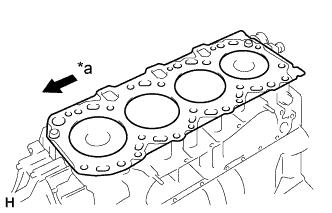
Place a new cylinder head gasket in position on the cylinder block.
Note
Be careful of the installation direction.
Text in Illustration *a Front -
Place the cylinder head in position on the cylinder head gasket.
-
Install the cylinder head bolts.
Tech Tips
-
The cylinder head bolts are tightened in 3 progressive steps (steps (2), (e) and (f).
-
If any bolts is broken or deformed, replace it.
-
Apply a light coat of engine oil on the threads and under the heads of the cylinder head bolts.
-
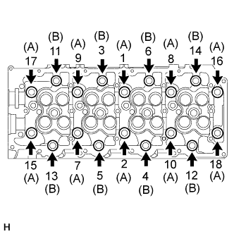
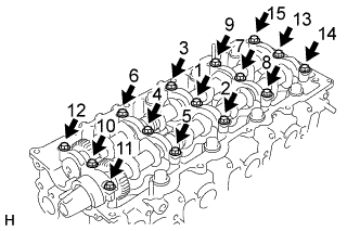
Install and uniformly tighten the 18 cylinder head bolts, in several passes, in the sequence shown.
- Torque:
- 85 N*m { 867 kgf*cm, 63 ft.*lbf }
Tech Tips
Each bolt length is indicated in the illustration.
Bolt length 107 mm (4.12 in.) for A 127 mm (5.00 in.) for B If any one of the cylinder head bolts does not meet the torque specification, replace the cylinder head bolt.
-
-
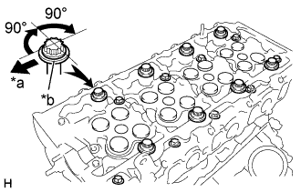
Text in Illustration *a Front *b Painted Mark Mark the front of the cylinder head bolt with paint.
-
Retighten the cylinder head bolts 90° in the numerical order shown.
-
Retighten cylinder head bolts by an additional 90°.
-
Check that the painted mark is now facing rearward.
-
-
INSTALL CAMSHAFT
-
Text in Illustration *1 Key Groove Rotate the crankshaft about 90° counterclockwise from the TDC position to lower the piston.
-
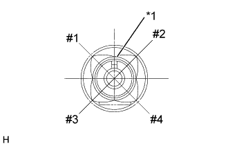
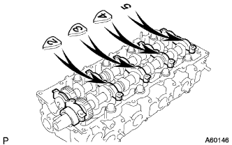
Place the camshaft No. 1 with its cam lobs #3 and #4 facing downward on the cylinder head as shown in the illustration.
-
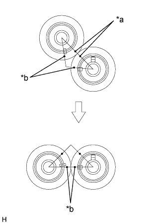
Text in Illustration *a Gear Point Mark *b Timing Mark Mesh the gear point marks of the camshaft No. 1 and No. 2.
-
Rotate the camshaft No. 2 with its gear in mesh to place it on the journal of exhaust side cylinder head as shown in the illustration.
-
Remove any old packing (FIPG) material and be careful not to drop any oil on the contact surfaces of the bearing cap No. 1 and cylinder head.
-
Using a razor blade and gasket scraper, remove all the old packing (FIPG) material from the gasket surfaces and sealing groove.
-
Thoroughly clean all components to remove all the loose material.
-
Using a non-residue solvent, clean both sealing surfaces.
-
-
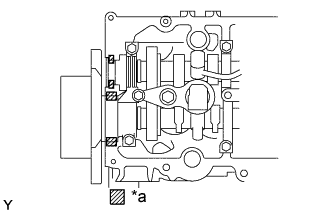
Text in Illustration *a Seal Packing *b Seal Width: 4 mm Apply seal packing to the camshaft bearing cap No. 1 as shown in the illustration.
-
Remove any old packing (FIPG) material and be careful not to drop any oil on the contact surfaces of the bearing cap and cylinder head.
Using a razor blade and gasket scraper, remove all the old packing (FIPG) material from the gasket surfaces and groove.
Thoroughly clean all components to remove all the loose material.
Using a non-residue solvent, clean both sealing surfaces.
-
Apply seal packing to the bearing cap as shown in the illustration.
Install a nozzle that has been cut to a 4 mm (0.16 in.) opening.
Parts must be assembled within 5 minutes of application. Otherwise the material must be removed and reapplied.
Immediately remove nozzle from the tube and reinstall cap.
Seal packing Toyota Genuine Seal Packing Black, Three Bond 1207B or equivalent Note
Prevent FIPG from being stuck to the oil passage of the bearing cap No. 1.
-
-
Install the 5 bearing caps in their proper locations.
-
Install and uniformly tighten the 10 bearing cap bolts in several passes in the sequence shown.
- Torque:
- 19 N*m { 194 kgf*cm, 14 ft.*lbf }
-
Install the camshaft oil seal.
-
Apply MP grease to a new oil seal lip.
-
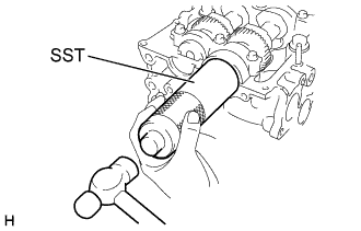
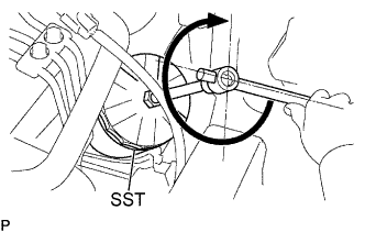
Using SST and a hammer, tap in the oil seal until its surface is flush with the oil seal retainer edge.
- SST
- 09608-06041
-
-
-
INSTALL COMMON RAIL ASSEMBLY
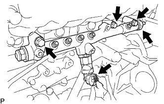
-
Install the common rail assembly with the 3 bolts.
- Torque:
- 38 N*m { 387 kgf*cm, 28 ft.*lbf }
-
Connect the sensor connectors.
-
-
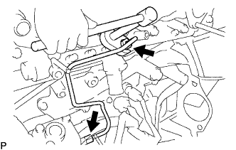
INSTALL NOZZLE LEAKAGE PIPE ASSEMBLY NO.2
- Torque:
- Bolt
- 12.7 N*m { 130 kgf*cm, 9 ft.*lbf }
- Union bolt
- 12.7 N*m { 130 kgf*cm, 9 ft.*lbf }
- Check valve
- 21 N*m { 214 kgf*cm, 15 ft.*lbf }
-
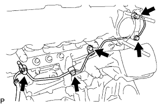
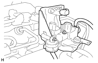
INSTALL FUEL INLET PIPE SUB-ASSEMBLY
-
Temporarily install the fuel inlet pipe sub-assembly.
-
Using a union wrench 17 mm, tighten the fuel inlet pipe sub-assembly union of common rail side.
- Torque:
- 31.9 N*m { 325 kgf*cm, 23 ft.*lbf, for use with SST }
- 35 N*m { 357 kgf*cm, 26 ft.*lbf }
Tech Tips
Use a torque wrench with a fulcrum length of 30 cm (11.81 in)..
-
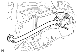
Using a union wrench 17 mm, tighten the fuel inlet pipe sub-assembly union of injection pump side.
- Torque:
- 31.9 N*m { 325 kgf*cm, 23 ft.*lbf, for use with SST }
- 35 N*m { 357 kgf*cm, 26 ft.*lbf }
-
Install the injection pipe clamp to the fuel inlet pipe sub- assembly.
Tech Tips
Use a torque wrench with a fulcrum length of 30 cm (11.81 in)..
-
-
INSTALL INTAKE MANIFOLD
-
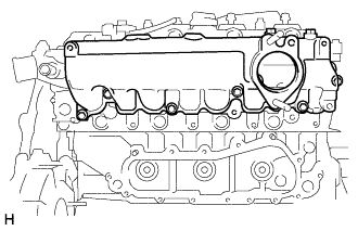
Install a new gasket and intake manifold with the 4 bolts and 2 nuts.
- Torque:
- 29 N*m { 296 kgf*cm, 21 ft.*lbf }
-
-
INSTALL OIL FILTER SUB-ASSEMBLY
-
Tighten the oil filter by hand until the rubber gasket contacts the seat of the filter mounting.
-
Using SST, give it an additional 3/4 turn to seat the filter.
- SST
- 09228-10002
- Torque:
- 17 N*m { 173 kgf*cm, 13 ft.*lbf }
-
-
INSTALL VSV ASSEMBLY
-
Install the VSV assembly and 2 bolts.
- Torque:
- 29 N*m { 296 kgf*cm, 21 ft.*lbf }
-
-
INSTALL EGR PIPE SUB-ASSEMBLY NO.1
-
Install the 2 gaskets, EGR control valve and EGR pipe sub-assembly.
-
Install the 2 nuts.
- Torque:
- 13 N*m { 133 kgf*cm, 9.6 ft.*lbf }
-
-
INSTALL TIMING BELT NO.2 COVER
-
Remove any old packing (FIPG) material and be careful not to drop any oil on the contact surfaces of timing gear cover and timing belt No. 2 cover.
-
Using a razor blade and gasket scraper, remove all the old packing (FIPG) material from the gasket surfaces and sealing groove.
-
Thoroughly clean all components to remove all the loose material.
-
Using a non-residue solvent, clean both sealing surfaces.
-
-
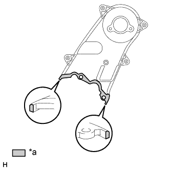
Text in Illustration *a Seal Packing Apply seal packing to the timing gear cover as shown in the illustration.
Seal packing Toyota Genuine Seal Packing Black, Three Bond 1207B or equivalent
-
Parts must be assembled within 5 minutes of application. Otherwise the material must be removed and reapplied.
-
Immediately remove nozzle from the tube and reinstall cap.
-
-
Install the timing belt No. 2 cover with the 4 bolts and nut.
- Torque:
- 10 N*m { 102 kgf*cm, 7 ft.*lbf }
-
-
INSTALL CAMSHAFT TIMING PULLEY
-
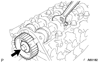
Install the set key to the key groove of the camshaft.
-
Align the set key with the key groove of the timing pulley.
-
Hold the hexagon wrench head portion of the camshaft, and install the timing pulley with the bolt.
- Torque:
- 98 N*m { 1000 kgf*cm, 72 ft.*lbf }
-
-
INSTALL INJECTOR ASSEMBLY
-
INSTALL CYLINDER HEAD COVER SUB-ASSEMBLY
-
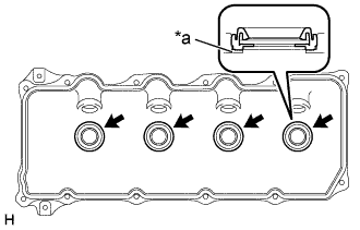
Text in Illustration *a Upper Side of Cylinder Head Cover Install 4 new No. 3 cylinder head cover gaskets to the cylinder head cover as shown in the illustration.
Note
-
Do not install the gaskets at an angle.
-
Keep the lip of the gasket free from foreign materials.
-
-
Install a new cylinder head cover gasket to the cylinder head cover.
-
Text in Illustration *a Seal Packing Apply seal packing to the cylinder head as shown in the illustration.
Seal packing: Toyota Genuine Seal Packing Black, Three Bond 1207B or equivalent -
Install the cylinder head cover with the 10 bolts and 2 nuts.
- Torque:
- 9.0 N*m { 92 kgf*cm, 78 in.*lbf }
-
Install the 4 nozzle holder seals.
-
Install the 4 injection pipes Click here.
-
Connect the engine wire protector and install the 2 bolts.
-
Connect the 4 injector connectors.
-
-
INSTALL INTAKE AIR CONNECTOR
-
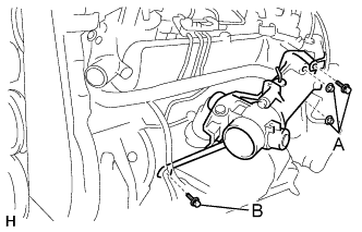
Install the intake air connector with diesel throttle body assembly, new gasket, 2 bolts and 2 nuts.
- Torque:
- A
- 20 N*m { 204 kgf*cm, 15 ft.*lbf }
- B
- 19 N*m { 194 kgf*cm, 14 ft.*lbf }
-
Connect the connector and hose.
-
Connect the throttle control motor connector.
-
Connect the throttle full switch connector.
-
Connect the Intake air temp. sensor connector.
-
Connect the vacuum hose.
-
-
-
INSTALL RADIATOR HOSE OUTLET
-
INSTALL HEATER WATER OUTLET HOSE A (FROM HEATER UNIT)
-
INSTALL AIR HOSE NO.3
-
INSTALL TURBOCHARGER SUB-ASSEMBLY
-
INSTALL AIR HOSE NO.1
-
INSTALL REAR HEATER WATER INLET HOSE A (FROM ENGINE)
-
INSTALL EXHAUST PIPE ASSEMBLY FRONT
-
INSTALL AIR CLEANER HOSE NO.2
-
INSTALL AIR CLEANER PIPE
-
INSTALL TIMING BELT
-
REFILL ENGINE COOLANT
-
Slowly fill the system with coolant.
-
Use of improper coolants may damage engine cooling system.
-
Use "Toyota Long Life Coolant" or equivalent and mix it with plan water according to the manufacturer's directions.
-
Using of coolant which includes more than 50 % [freezing protection down to -35°C (-31°F)] or 60 % [freezing protection down to -50°C (-58°F)] of ethylene-glycol is recommended but not more than 70 %.
Note
-
Do not use an alcohol type coolant or plain water alone.
-
The coolant should be mixed with plain water (preferably demineralized water or distilled water).
Capacity: w/ Front heater
w/o heater
10.1 liters (10.5 US qts, 8.7 Imp. qts)
9.2 liters (9.51 US qts, 7.9 Imp. qts)
w/ Front and Rear
heater
10.9 liters (11.5 US qts, 8.9 Imp. qts)
-
-
Reinstall the radiator cap.
-
Start the engine, and bleed the cooling system.
-
Refill the radiator reservoir with coolant until it reaches the "full" line.
-
-
BLEED INJECTION PIPE
-
Move the priming pump of the fuel filter up and down until it becomes hard.
-
-
CHECK ENGINE COOLANT LEAK
-
INSPECT FUEL LEAK
CAUTION:
-
During ACTIVE TEST mode, engine speed goes high and combustion noise becomes loud, so pay attention.
-
During ACTIVE TEST mode, fuel becomes high pressure, so take much care not to expose your eyes, hands, or body to the fuel.
-
Check that there are no leaks from any part of the fuel system when the engine stops.
If there is fuel leakage, replace those parts.
-
While cranking or starting the engine, check that there are no leaks from any part of the fuel system.
If there is fuel leakage, replace those parts.
-
Disconnect the return hose from the common rail.
-
While cranking the engine, check fuel leakage from the return pipe.
If there is fuel leakage, replace the common rail assembly Click here.
-
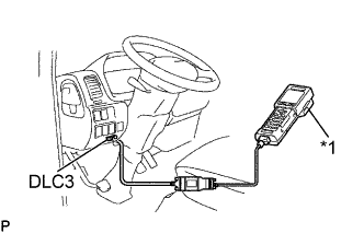
Text in Illustration *1 Intelligent Tester Connect the intelligent tester to the DLC3.
-
Start the engine and push the intelligent tester main switch ON.
-
Select the FUEL LEAK test of ACTIVE TEST mode on the intelligent tester.
-
If you have no intelligent tester, depress the accelerator pedal quickly and fully to increase the engine speed at maximum and keep it for 2 seconds. Repeat this operation several times.
-
Check that there are no leaks from any part of the fuel system.
Note
If the leakage from the return pipe is less than 10 cc (0.6 cu in.) in a minute, it is acceptable.
If there is fuel leakage, replace those parts.
-
Reconnect the return hose to the common rail.
-
-
CHECK EXHAUST GAS LEAK