REAR SEAT OUTER BELT ASSEMBLY(for 3 Door) INSTALLATION

CAUTION / NOTICE / HINT
CAUTION:
Some of these service operations affect the SRS airbag system. Read the precautionary notices concerning the SRS airbag system before servicing Click here.
Tech Tips
The procedure described below is for the RH side. Use the same procedure for both the LH and RH sides, unless otherwise specified.
PROCEDURE
-
INSTALL REAR SEAT 3 POINT TYPE OUTER BELT ASSEMBLY
-
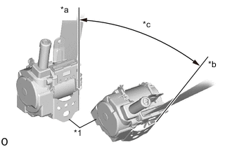
*1 Retractor *a Unlock *b Lock *c 45° Check the angle of inclination required to lock the retractor.
-
Gently incline the retractor from its initial position. Check that the belt does not lock when the retractor is inclined 15° or less in any direction. Also, check that the belt locks when the inclination of the retractor is 45° or more.
Note
Do not disassemble the retractor.
If the operation is not as specified, replace the rear seat 3 point type outer belt assembly.
-
-
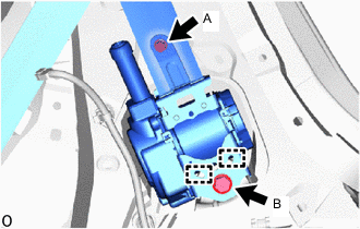
Engage the 2 hooks and temporarily install the rear seat 3 point type outer belt assembly with the 2 bolts.
-
Tighten bolt A and then bolt B.
- Torque:
- for bolt A
- 12.5 N*m { 127 kgf*cm, 9 ft.*lbf }
- for bolt B
- 42 N*m { 428 kgf*cm, 31 ft.*lbf }
-
Install the floor anchor with the bolt.
- Torque:
- 42 N*m { 428 kgf*cm, 31 ft.*lbf }
-
Connect the floor anchor with the bolt.
-
Check that the ELR locks.
Note
-
The check should be performed with the rear seat 3 point type outer belt assembly installed.
-
Do not allow the anchor part of the rear seat 3 point type outer belt assembly and the protruding parts of the floor panel to overlap.
-
With the belt installed, check that the belt locks when it is pulled out quickly.
If the operation is not as specified, replace the rear seat 3 point type outer belt assembly.
-
-
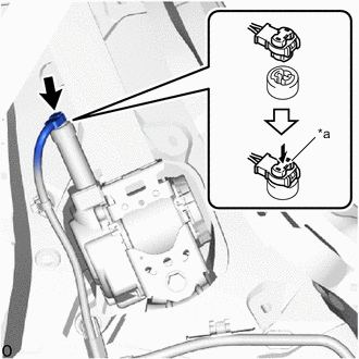
*a Locking Button Connect the pretensioner connector.
-
Lock the locking button.
Note
Securely lock the locking button.
-
Remove the bolt and floor anchor.
-
-
INSTALL ROOF SIDE INNER GARNISH
-
INSTALL DECK TRIM SIDE PANEL ASSEMBLY RH (for RH Side)
-
INSTALL DECK TRIM SIDE PANEL ASSEMBLY LH (for LH Side)
-
CONNECT REAR SEAT 3 POINT TYPE OUTER BELT ASSEMBLY
-
INSTALL FRONT QUARTER TRIM PANEL ASSEMBLY
-
CONNECT FRONT SEAT OUTER BELT ASSEMBLY
-
CONNECT FRONT DOOR OPENING TRIM WEATHERSTRIP
-
Connect the front door opening trim weatherstrip.
-
-
INSTALL FRONT DOOR SCUFF PLATE
-
INSTALL REAR FLOOR FINISH PLATE
-
INSTALL JACK HANDLE (for RH Side)
-
INSTALL NO. 2 ROOM LIGHT ASSEMBLY (for LH Side)
-
INSTALL SPARE WHEEL COVER (w/ Cover)
-
INSTALL DECK BOARD ASSEMBLY (w/ Deck Board)
-
INSTALL REAR SEAT ASSEMBLY (for RH Side)
-
INSTALL REAR SEAT ASSEMBLY (for LH Side)
-
CONNECT CABLE TO NEGATIVE BATTERY TERMINAL
- Torque:
- 5.4 N*m { 55 kgf*cm, 48 in.*lbf }
-
INSPECT SRS WARNING LIGHT