MANUAL TRANSAXLE ASSEMBLY(When Using the Engine Support Bridge for 2ZR-FE) REMOVAL

PROCEDURE
-
PRECAUTION
Note
-
When the transaxle is removed, be sure to use a new clutch release cylinder with bearing assembly and new installation bolts. Removal of the transaxle allows the compressed clutch release cylinder with bearing assembly to return to its original position, and dust from the moving section could damage the seal of the clutch release cylinder with bearing assembly, possibly causing clutch fluid leaks.
-
After turning the ignition switch off, waiting time may be required before disconnecting the cable from the battery terminal. Therefore, make sure to read the disconnecting the cable from the battery terminal notice before proceeding with work.
-
-
DISCONNECT CABLE FROM NEGATIVE BATTERY TERMINAL
Note
When disconnecting the cable, some systems need to be initialized after the cable is reconnected.
Click here
-
REMOVE ENGINE UNDER COVER LH
-
REMOVE ENGINE UNDER COVER RH
-
DRAIN TRANSAXLE OIL
-
REMOVE WINDSHIELD WIPER MOTOR AND LINK
-
REMOVE FRONT NO. 1 VENTILATOR SEAL (for LHD)
-
REMOVE FRONT NO. 1 VENTILATOR SEAL (for RHD)
-
REMOVE FRONT AIR SHUTTER SEAL RH (for LHD)
-
REMOVE FRONT AIR SHUTTER SEAL RH (for RHD)
-
REMOVE INNER COWL TOP TO COWL BRACE (for LHD)
-
REMOVE INNER COWL TOP TO COWL BRACE (for RHD)
-
REMOVE OUTER COWL TOP PANEL (for LHD)
-
REMOVE OUTER COWL TOP PANEL (for RHD)
-
REMOVE FRONT SUSPENSION UPPER CENTER BRACE SUB-ASSEMBLY
-
DISCONNECT NO. 2 VENTILATION HOSE
-
REMOVE AIR CLEANER CAP WITH AIR CLEANER HOSE
-
REMOVE AIR CLEANER FILTER ELEMENT SUB-ASSEMBLY
-
REMOVE AIR CLEANER CASE SUB-ASSEMBLY
-
REMOVE AIR CLEANER BRACKET
-
Disengage the clamp.
-
Remove the 2 bolts and the air cleaner bracket.
-
-
REMOVE BATTERY
-
REMOVE BATTERY TRAY
-
REMOVE BATTERY CARRIER
-
REMOVE REAR CONSOLE BOX
-
DISCONNECT NO. 3 ENGINE WIRE
-
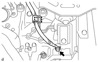
Disengage the clamp.
-
Remove the bolt and disconnect the No. 3 engine wire from the manual transaxle assembly.
-
-
DISCONNECT ENGINE WIRE
-
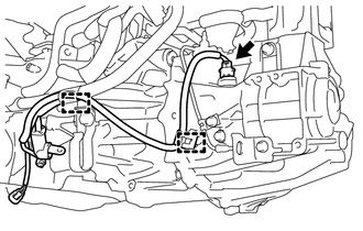
Disengage the 2 clamps and disconnect the connector.
-
-
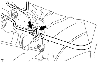
SEPARATE CLUTCH HOSE
-
Using a 10 mm union nut wrench, separate the clutch release cylinder to flexible hose tube from the clutch hose.
-
Remove the clip and separate the clutch hose from the flexible hose bracket.
-
-
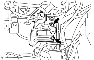
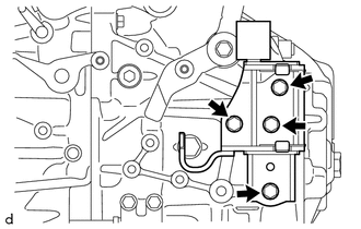
DISCONNECT TRANSMISSION CONTROL CABLE ASSEMBLY
-
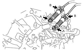
Remove the 2 clips A to disconnect the transmission control cable assembly from the manual transaxle assembly.
-
Remove the 2 clips B to disconnect the transmission control cable assembly from control cable bracket assembly.
-
-
REMOVE STARTER ASSEMBLY
-
REMOVE FLYWHEEL HOUSING SIDE COVER
-
REMOVE FRONT DRIVE SHAFT ASSEMBLIES
-
REMOVE FRONT FLOOR CENTER BRACE
-
REMOVE FRONT EXHAUST PIPE ASSEMBLY
-
INSTALL ENGINE HANGER
-
INSTALL ENGINE SUPPORT BRIDGE
-
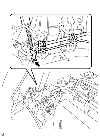
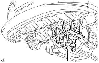
*1 Suction Tube Sub-assembly B *2 Liquid Tube Sub-assembly A Remove the bolt.
-
Disengage the 4 clamps to separate the suction tube sub-assembly B and the liquid tube sub-assembly A.
-
Remove the hood support rod.
-
Install the 2 nuts to the front suspension upper brace bracket in order to set the sub beam of the SST in place.
Tech Tips
Use the nut for securing the front suspension upper center brace sub-assembly in place.
-
Install SST to the vehicle body as shown in the illustration.
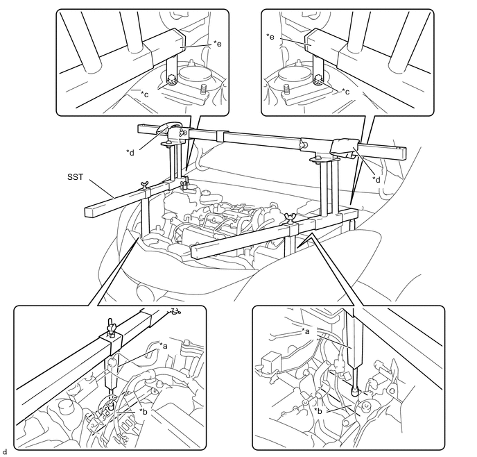
*a Support Shaft *b Front Side Member *c Front Suspension Nut *d Pieces of Cloth *e Sub Beam - - - SST
- 09940-10020
Note
-
Prevent SST from contacting the vehicle body exterior and windshield glass.
-
To prevent damage to the engine hood, place pieces of cloth between the engine hood and SST.
-
Lightly shake SST by hand to make sure it is securely installed before performing work.
-
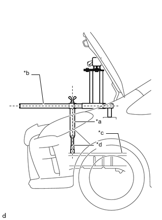
*a Support Shaft *b Sub Beam *c Front Side Member *d Threaded Portion Turn the threaded portion of each support shaft to adjust its height until the sub beams are parallel to the ground.
-
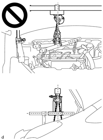
Install the chain block to the sling bracket.
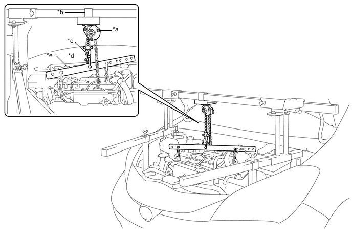
*a Chain Block *b Sling Bracket *c Fuse Shackle *d Shackle (A) *e Division Bar - - -
Install the division bar to the chain block with the shackles.
-
Connect the division bar to the alternator tensioner bracket with the shackle (A) and chain.
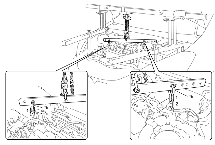
*1 Alternator Tensioner Bracket *2 Engine Hanger *a Division Bar *b Shackle (A) *c Chain - - -
Connect the division bar to the engine hanger with the shackle (A) and chain.
Note
Connect the 2nd link of the chain to the engine hanger.
-
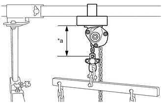
*a 120 mm (4.72 in.) or more Make sure the distance between the chain block assembly and suspension ring is 120 mm (4.72 in.) or more.
Tech Tips
If the suspension height is less than 120 mm, adjust the links of the chain which connect the division bar and engine hanger.
-
Adjust the positions of the chain block assembly, support brackets and main beam so that the chain of the chain block assembly is perpendicular to the main beam and the length of the main beam on the outer side of the support bracket LH and RH is the same as shown in the illustration.
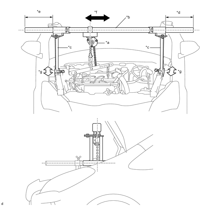
*a Chain Block *b Main Beam *c Support Bracket *d Dimension (A) *e Dimension (B) *f Right to Left Adjustment *g Front to Rear Adjustment - - Note
-
If the chain of the chain block is tilted, do not perform work.
-
If the engine mount is removed with the chain of the chain block tilted, the engine assembly with transaxle may interfere with the vehicle.
-
-
Confirm the appropriate installation state of the engine support bridge and tighten the 6 wing bolts and 2 bolts.
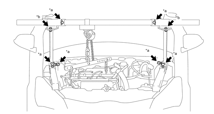
*a Wing Bolt *b Bolt - Torque:
- Bolt
- 30 N*m { 306 kgf*cm, 22 ft.*lbf }
CAUTION:
-
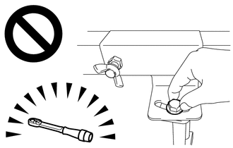
Do not perform any procedures before tightening the bolts to the specified torque.
-
Performing procedures without tightening the bolts to the specified torque, may cause the engine support bridge to fall.
-
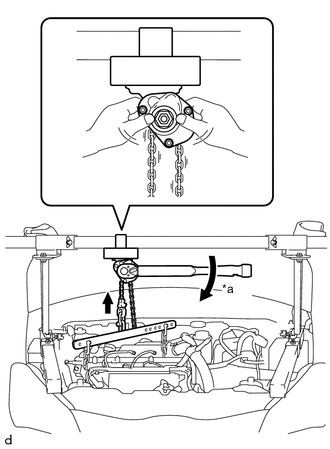
*a Turn Tighten the chain block assembly until it cannot be moved any further by hand.
-
-
REMOVE FRONT SUSPENSION CROSSMEMBER SUB-ASSEMBLY
-
REMOVE ENGINE MOVING CONTROL ROD BRACKET
-
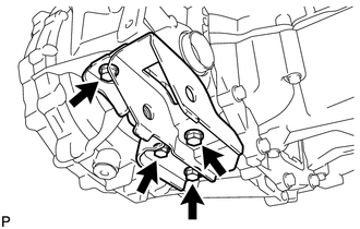
Remove the 4 bolts and the engine moving control rod bracket from the manual transaxle assembly.
-
-
SUPPORT MANUAL TRANSAXLE ASSEMBLY
-
*a Lashing Belt Support the manual transaxle assembly with a transmission jack so that it is stable.
Note
Using a lashing belt or a rope, fix the manual transaxle assembly to the transmission jack.
-
-
REMOVE ENGINE MOUNTING INSULATOR LH
-
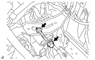
Remove the bolt and nut and separate the engine mounting insulator LH from the engine mounting bracket sub-assembly LH.
Note
Turn the bolt while holding the nut.
-
Remove the 5 bolts and the engine mounting insulator LH.
-
-
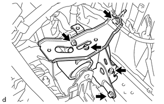
REMOVE ENGINE MOUNTING BRACKET SUB-ASSEMBLY LH
-
Remove the 4 bolts and the engine mounting bracket sub-assembly LH from the manual transaxle assembly.
-
-
REMOVE MANUAL TRANSAXLE ASSEMBLY
-
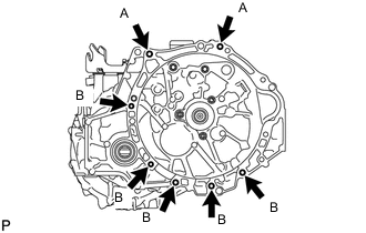
Remove the 7 bolts and the manual transaxle assembly.
Note
-
To avoid damage to the knock pins, do not pry between the transaxle and the engine.
-
To avoid damage to the input shaft, do not forcefully shake the transaxle.
Tech Tips
-
Bolt (A): Remove from manual transaxle assembly side.
-
Bolt (B): Remove from engine assembly side.
-
-
-
REMOVE WIRE HARNESS CLAMP BRACKET
-
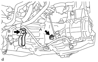
Remove the bolt A and wire harness clamp bracket.
-
Remove the bolt B, wire harness clamp bracket and radiator hose clamp bracket.
-
-
REMOVE SPEEDOMETER DRIVEN HOLE COVER SUB-ASSEMBLY
-
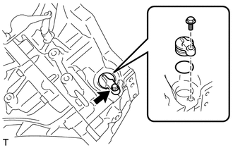
Remove the bolt and the speedometer driven hole cover sub-assembly from the manual transaxle assembly.
-
Remove the O-ring from the speedometer driven hole cover sub-assembly.
-
-
REMOVE CLUTCH RELEASE CYLINDER TO FLEXIBLE HOSE TUBE
-
REMOVE CLUTCH RELEASE BLEEDER SUB-ASSEMBLY
-
REMOVE CLUTCH TUBE BOOT
-
REMOVE CLUTCH RELEASE CYLINDER WITH BEARING ASSEMBLY
-
REMOVE CLUTCH RELEASE CYLINDER TO BLEEDER TUBE
-
REMOVE CLUTCH FLEXIBLE HOSE BRACKET