CANISTER(for TMMF Made) INSTALLATION

CAUTION / NOTICE / HINT
Tech Tips
If the fuel pump has been replaced, conduct Inspection After Repairs Click here.
PROCEDURE
-
INSTALL CHARCOAL CANISTER SUB-ASSEMBLY
-
Install a new O-ring to the charcoal canister sub-assembly.
-
Engage the 2 claws of the No. 1 fuel suction support guide and the 3 claws of the No. 1 fuel suction support, and install the No. 1 fuel suction support to the charcoal canister sub-assembly.
-
-
INSTALL FUEL PRESSURE REGULATOR ASSEMBLY
-
INSTALL NO. 2 FUEL SUCTION SUPPORT
-
INSTALL FUEL PUMP
-
INSTALL FUEL PUMP HARNESS
-
INSTALL FUEL SENDER GAUGE ASSEMBLY
-
INSTALL FUEL SUCTION TUBE SET GASKET
-
Coat a new fuel suction tube gasket with gasoline and install it to the fuel tank.
-
-
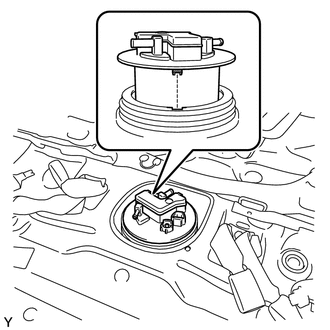
INSTALL FUEL SUCTION TUBE ASSEMBLY WITH PUMP AND GAUGE
Tech Tips
If the fuel pump has been replaced, conduct Inspection After Repairs Click here.
-
Pass the float of the fuel sender gauge assembly into the fuel tank.
-
Bend up the tip of the fuel pump filter and set the fuel suction tube assembly on the fuel tank.
Note
Be careful not to bend the arm of the fuel sender gauge assembly.
-
-
INSTALL FUEL PUMP GAUGE RETAINER
-
Align the tab of the fuel suction tube assembly with the groove of the fuel tank.
-
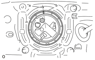
Text in Illustration *a Start of Threads
(Fuel Tank)
*b Start of Threads
(Fuel Pump Gauge Retainer)
Align the retainer mark (start of threads) with the start of the threads on the fuel tank, and while pressing down on the fuel suction tube assembly, install the new fuel pump gauge retainer and tighten it by hand as much as possible.
-
Install SST to the fuel pump gauge retainer.
- SST
- 09808-14030 ( 09808-01010, 09808-01020, 09808-01030, 09808-01040, 09808-01050 )
-
Temporarily install plate and claw to the fuel pump gauge retainer.
-
Press claw against the rib of the fuel pump gauge retainer, and tighten bolt.
-
Install handle.
-
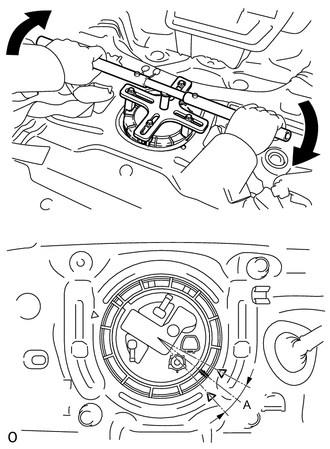
While making sure that SST does not rise up, slowly turn handle and tighten until the mark on the fuel pump gauge retainer is within range A as shown in the illustration.
Note
-
Be careful not to apply excessive downward force to SST, as this may damage the fuel pump or fuel tank.
-
Turning SST at an angle may cause it to slip off of the fuel pump gauge retainer, so be sure SST is horizontal when turning.
-
To prevent damage to parts, do not turn SST too vigorously.
-
If SST slips off of the fuel pump gauge retainer, loosen bolt and install SST again.
-
-
-
CONNECT NO. 1 CANISTER OUTLET HOSE SUB-ASSEMBLY
-
Connect the No. 1 canister outlet hose sub-assembly to the fuel suction tube with pump and gauge.
-
-
CONNECT NO. 2 FUEL EMISSION TUBE
-
Connect the No. 2 fuel emission tube to the fuel suction tube with pump and gauge.
-
-
CONNECT FUEL TANK MAIN TUBE SUB-ASSEMBLY
-
Connect the fuel tank main tube sub-assembly to the fuel suction tube with pump and gauge.
-
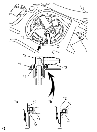
Text in Illustration *1 Tube Joint Clip *2 Fuel Tube Joint *3 Fuel Tube *4 Fuel Suction Plate *a OK *b NG *c Rib Install the fuel joint clip.
Note
-
Make sure there is no damage to or foreign matter on the connecting surfaces.
-
Check that the fuel tube joint is correctly and fully inserted.
-
Check that the main joint clip is above the rib of the main tube.
-
After installing the tube joint clip, make sure the fuel tube joint will not come out.
-
Do not damage any of the clips. If a clip is damaged, replace it.
-
-
-
INSTALL REAR FLOOR SERVICE HOLE COVER
-
Connect the fuel pump connector to the fuel suction tube with pump and gauge.
-
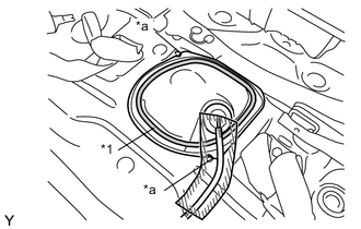
Text in Illustration *1 Butyl Tape *a Mach Mark Apply butyl tape to the location shown in the illustration, align the matchmarks, and install the rear service hole cover.
-
-
CONNECT CABLE TO NEGATIVE BATTERY TERMINAL
- Torque:
- 5.4 N*m { 55 kgf*cm }
-
ADD FUEL
-
CHECK FUEL PUMP OPERATION AND FUEL LEAKS
-
INSTALL REAR SEATBACK CENTER HINGE SUB-ASSEMBLY
-
INSTALL REAR SEAT ASSEMBLY LH
-
INSTALL REAR SEAT ASSEMBLY RH
-
INSTALL SPARE WHEEL COVER
-
INSTALL DECK BOARD ASSEMBLY