FUEL SENDER GAUGE ASSEMBLY INSTALLATION

PROCEDURE
-
INSTALL FUEL SENDER GAUGE ASSEMBLY
-
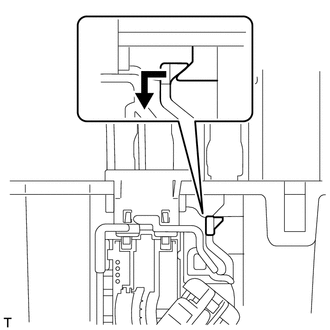
Install the fuel sender gauge by sliding it downward.
-
Connect the fuel sender gauge connector and engage the harness clamp.
-
-
INSTALL FUEL SUCTION TUBE SET GASKET
-
Install a new fuel tank suction tube gasket onto the fuel tank.
-
-
INSTALL FUEL TANK VENT TUBE ASSEMBLY WITH SENDER GAUGE
-
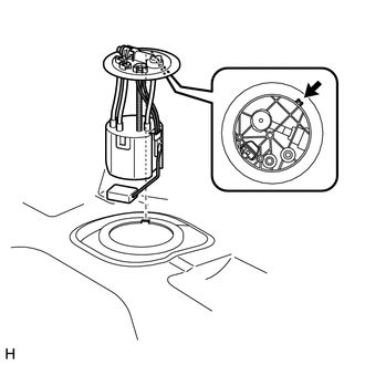
Align the protrusion of the fuel tank vent tube assembly with sender gauge with the cutout of the fuel tank and install the fuel tank vent tube assembly with sender gauge.
Note
-
Do not bend the arm of the sender gauge.
-
Ensure that the fuel suction tube gasket is in the correct position.
-
-
-
INSTALL FUEL PUMP GAUGE RETAINER
-

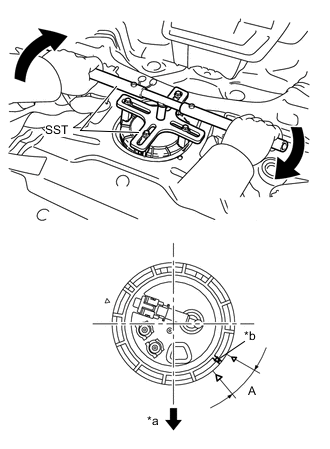
Text in Illustration *a Screw Starting Point
(Fuel Tank Side)
*b Screw Starting Point
(Fuel Pump Gauge Retainer Side)
*c Front of Vehicle While holding the fuel suction tube assembly with pump and gauge by hand to prevent it from tilting, align the mark on the new fuel pump gauge retainer with the start mark on the fuel tank and tighten the fuel pump gauge retainer 180° by hand.
Tech Tips
Check that there is no damage, dents, foreign matter or other defects on the threads of the fuel tank.
-
Text in Illustration *a Front of Vehicle *b Mark Temporarily install the SST plate and claws to the fuel pump gauge retainer.
- SST
- 09808-14030 ( 09808-01010, 09808-01020, 09808-01030, 09808-01040, 09808-01050 )
Tech Tips
Engage the SST claws securely with the fuel pump gauge retainer ribs to secure SST.
-
While pressing the claws of SST to the fuel pump gauge retainer ribs securely, tighten the bolts.
Tech Tips
Install SST while pressing the SST claws toward the fuel pump gauge retainer (toward the center of SST).
-
Install the SST handle.
-
Lightly press down on SST to prevent it from separating from the retainer. While pressing SST, rotate the handle slowly to tighten the retainer.
-
-
CONNECT FUEL RETURN TUBE SUB-ASSEMBLY
-
Insert the fuel return tube.
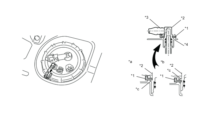
Text in Illustration *1 Tube Joint Clip *2 Fuel Tube Joint *3 Fuel Tube Connector *a OK *b NG *c Rib -
Install the tube joint clip.
Note
-
Check that there are no scratches or foreign objects on the connecting part.
-
Check that the fuel return tube is inserted securely.
-
Check that the tube joint clip is on the collar of the fuel return tube.
-
After installing the tube joint clip, check that the fuel return tube assembly is securely connected by pulling on it.
-
Do not damage any of the clips. If a clip is damaged, replace it.
-
-
-
CONNECT FUEL TANK MAIN TUBE SUB-ASSEMBLY
-
Insert the fuel tank main tube.
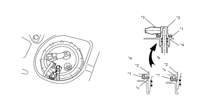
Text in Illustration *1 Tube Joint Clip *2 Fuel Tube Joint *3 Fuel Tube Connector *a OK *b NG *c Rib -
Install the tube joint clip.
Note
-
Check that there are no scratches or foreign objects on the connecting part.
-
Check that the fuel tank main tube is inserted securely.
-
Check that the tube joint clip is on the collar of the fuel tank main tube.
-
After installing the tube joint clip, check that the fuel tank main tube assembly is securely connected by pulling on it.
-
Do not damage any of the clips. If a clip is damaged, replace it.
-
-
-
INSTALL REAR FLOOR SERVICE HOLE COVER
-
Connect the fuel sender gauge connector.
-
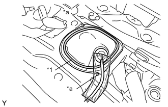
Text in Illustration *1 Butyl Tape *a Mach Mark Install the rear floor service hole cover with new butyl tape.
-
-
INSTALL REAR SEATBACK CENTER HINGE SUB-ASSEMBLY
-
INSTALL REAR SEAT ASSEMBLY LH
-
INSTALL REAR SEAT ASSEMBLY RH
-
INSTALL SPARE WHEEL COVER (for TMMF Made)
-
INSTALL DECK BOARD ASSEMBLY
-
BLEED AIR FROM FUEL SYSTEM
-
INSPECT FOR FUEL LEAK