ENGINE ASSEMBLY REMOVAL

CAUTION / NOTICE / HINT
CAUTION:
The engine assembly with transaxle is very heavy. Be sure to follow the procedure described in the repair manual, or the engine lifter may suddenly drop.
PROCEDURE
-
PRECAUTION
Note
After turning the engine switch off, waiting time may be required before disconnecting the cable from the negative (-) battery terminal. Therefore, make sure to read the disconnecting the cable from the negative (-) battery terminal notices before proceeding with work.
-
RECOVER REFRIGERANT FROM REFRIGERATION SYSTEM
-
DISCHARGE FUEL SYSTEM PRESSURE
-
ALIGN FRONT WHEELS FACING STRAIGHT AHEAD
-
DISCONNECT CABLE FROM NEGATIVE BATTERY TERMINAL
Note
When disconnecting the cable, some systems need to be initialized after the cable is reconnected.
-
REMOVE FRONT WHEELS
-
REMOVE ENGINE UNDER COVER LH
-
Remove the 3 bolts, 3 screws and engine under cover LH.
-
-
REMOVE ENGINE UNDER COVER RH
-
Remove the 2 bolts, screw engine under cover RH.
-
-
DRAIN ENGINE COOLANT
-
DRAIN SUPERCHARGER COOLANT
-
DRAIN ENGINE OIL
-
DRAIN MANUAL TRANSAXLE OIL
-
REMOVE WINDSHIELD WIPER LINK ASSEMBLY
-
REMOVE FRONT NO. 1 VENTILATOR SEAL
-
for TMMF made LHD:
-
for TMMF made RHD:
-
-
REMOVE FRONT AIR SHUTTER SEAL RH
-
for TMMF made LHD:
-
for TMMF made RHD:
-
-
REMOVE INNER COWL TOP TO COWL BRACE
-
for TMMF made LHD:
-
for TMMF made RHD:
-
-
REMOVE OUTER COWL TOP PANEL
-
for TMMF made LHD:
-
for TMMF made RHD:
-
-
REMOVE FRONT SUSPENSION UPPER CENTER BRACE SUB-ASSEMBLY
-
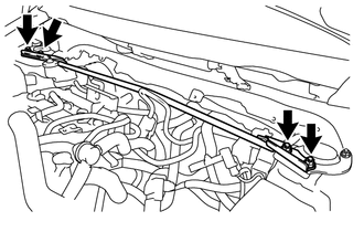
Remove the 4 nuts and front suspension upper center brace sub-assembly from the front suspension upper brace bracket LH and RH.
-
-
REMOVE AIR CLEANER CAP WITH AIR CLEANER HOSE
-
REMOVE AIR CLEANER FILTER ELEMENT SUB-ASSEMBLY
-
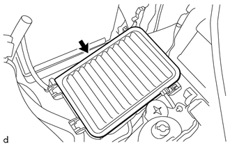
Remove the air cleaner filter element sub-assembly from the air cleaner case sub-assembly.
-
-
REMOVE AIR CLEANER CASE SUB-ASSEMBLY
-
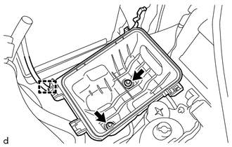
Disconnect the wire harness clamp from the air cleaner case sub-assembly.
-
Remove the 2 bolts and air cleaner case sub-assembly.
-
-
REMOVE BATTERY
-
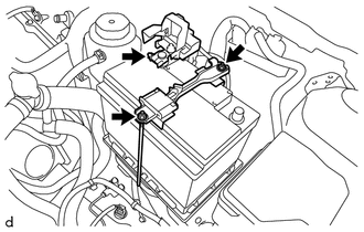
Loosen the nut, and disconnect the cable from the positive (+) battery terminal.
-
Remove the 2 nut and battery clamp sub-assembly.
-
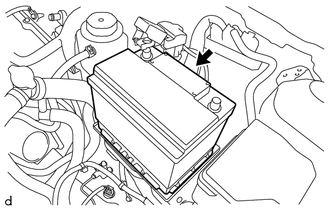
Remove the battery.
-
-
REMOVE BATTERY TRAY
-
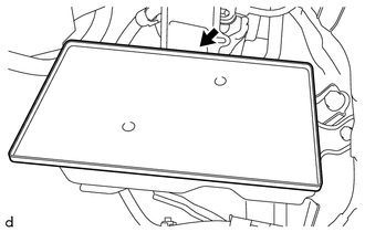
Remove the battery tray.
-
-
REMOVE BATTERY CARRIER
-
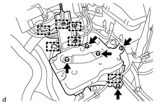
Disconnect the 6 wire harness clamps from the battery carrier.
-
Remove the 5 bolts and battery carrier.
-
-
DISCONNECT WIRE HARNESS
-
Disconnect the clamp and wire harness from the air cleaner blacket.
-
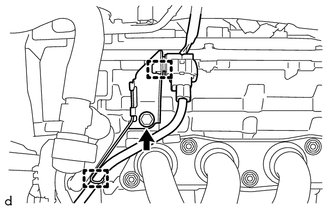
Pull up the lever to disconnect the ECM connector.
-
Disconnect the wire harness clamp.
-
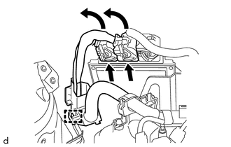
Remove the No. 1 engine room relay block cover from the engine room relay block and junction block assembly.
-
Disconnect the wire harness clamp.
-
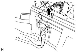
Disconnect the 2 wire harness connectors and wire harness from the engine room relay block and junction block assembly.
-
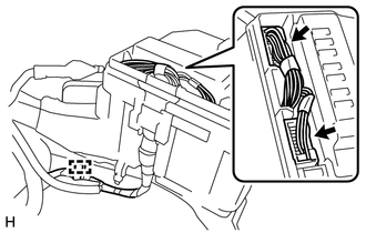
Disengage the 2 claws and wire harness from the engine room relay block and junction block assembly.
-
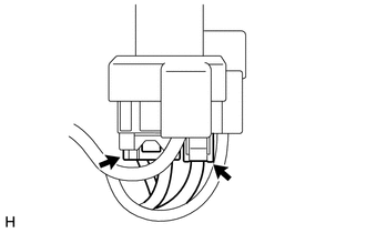
Disconnect the 2 wire harness connectors from the positive (+) battery terminal.
-
Remove the bolt and disconnect the 2 wire harness clamp from the manual transaxle assembly.
-
Disconnect all the wire harnesses and connectors.
-
-
REMOVE FAN AND GENERATOR V BELT
-
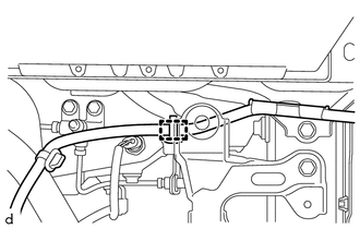
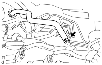
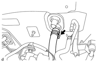
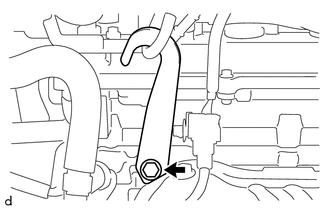
DISCONNECT NO. 3 RADIATOR HOSE
-
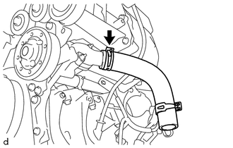
Slide the clip and disconnect the No. 3 radiator hose from the cylinder head sub-assembly.
-
-
DISCONNECT NO. 4 SUB-RADIATOR HOSE
-
DISCONNECT NO. 7 SUB-RADIATOR HOSE
-
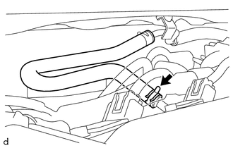
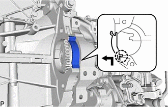
DISCONNECT RESERVE TANK INLET HOSE
-
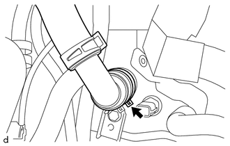
Slide the hose clip and disconnect the reserve tank inlet hose from the intercooler reserve tank assembly.
-
-
DISCONNECT RESERVE TANK OUTLET HOSE
-
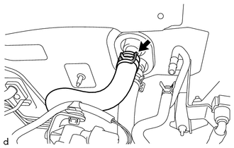
DISCONNECT RADIATOR HOSE
-
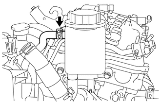
Slide the clip and disconnect the radiator hose from the water inlet.
-
-
DISCONNECT FUEL TUBE SUB-ASSEMBLY
-
REMOVE NO. 1 FUEL VAPOR FEED HOSE
-
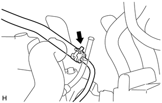
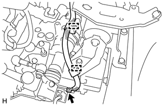
Slide the clip and disconnect the No. 1 fuel vapor feed hose from the vacuum switching valve assembly.
-
-
DISCONNECT UNION TO CHECK VALVE HOSE (for RHD)
-
Slide the clip and disconnect the union to check valve hose from the air tube.
-
-
DISCONNECT UNION TO CHECK VALVE HOSE (for LHD)
-
Slide the clip and disconnect the union to check valve hose from the air tube.
-
-
DISCONNECT OUTLET HEATER WATER HOSE
-
Slide the clip and disconnect the outlet heater water hose from the air conditioner unit assembly.
-
-
DISCONNECT INLET HEATER WATER HOSE
-
Slide the clip and disconnect the inlet heater water hose from the air conditioner unit assembly.
-
-
SEPARATE CLUTCH HOSE
-
REMOVE COMPRESSOR WITH PULLEY ASSEMBLY
-
REMOVE FRONT FLOOR CENTER BRACE
-
REMOVE REAR CONSOLE BOX ASSEMBLY
-
REMOVE FRONT EXHAUST PIPE ASSEMBLY
-
DISCONNECT TRANSMISSION CONTROL CABLE ASSEMBLY
-
REMOVE DRIVE SHAFT ASSEMBLY
-
REMOVE COLUMN HOLE COVER SILENCER SHEET
-
SEPARATE STEERING SLIDING YOKE SUB-ASSEMBLY
-
SEPARATE NO. 1 STEERING COLUMN HOLE COVER SUB-ASSEMBLY
-
REMOVE FRONT SUSPENSION MEMBER BRACE SUB-ASSEMBLY
-
REMOVE ENGINE ASSEMBLY WITH TRANSAXLE
-
Set an engine lifter.
Note
-
Using height adjustment attachments and plate lift attachments, place the engine assembly with transaxle horizontally.
-
To prevent the oil pan from deforming, do not place any attachments under the oil pan of the engine assembly with transaxle.
-
Do not perform any procedure while the engine assembly with transaxle is suspended because doing so may cause the engine assembly with transaxle to drop, resulting in injury. However, the engine assembly with transaxle needs to be suspended when it is installed to or removed from an engine stand.
-
-
Remove the 2 bolts and engine mounting stay.
-
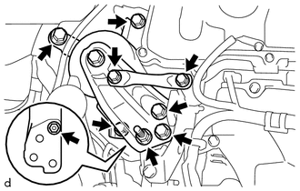
Remove the 5 bolt, 2 nuts and separate the engine mounting insulator sub-assembly RH.
-
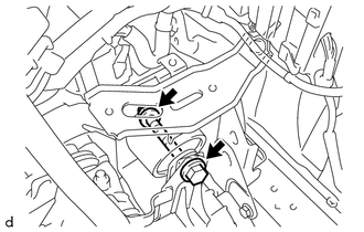
Remove the through bolt, nut and separate the engine mounting insulator LH.
Tech Tips
When removing the through bolt, keep the nut from rotating.
-
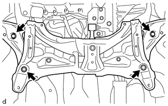
Remove the 4 bolt.
-
Carefully remove the engine assembly with transaxle from the vehicle.
Note
Make sure that the engine assembly with transaxle is clear of all wiring and hoses.
-
-
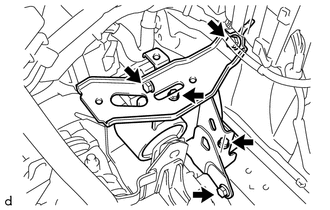
REMOVE WIRE HARNESS CLAMP BRACKET
-
Disengage the 2 clamps.
-
Remove the bolt and wire harness clamp bracket.
-
-
INSTALL ENGINE HANGER
-
Install the engine hanger with the bolt.
- Torque:
- 44 N*m { 449 kgf*cm, 32 ft.*lbf }
Tech Tips
Engine Hanger 12282-37011 Bolt 91552-81050 -
Attach an engine sling device and hang the engine assembly with transaxle with a chain block.
Note
-
Pay attention to the angle of the sling device as the engine assembly with transaxle or alternator tensioner bracket and engine hanger may be damaged or deformed if the angle is incorrect.
-
Do not perform any procedure while the engine assembly is suspended because doing so may cause the engine assembly to drop, resulting in injury. However, the engine assembly needs to be suspended when it is installed to or removed from an engine stand.
-
-
-
REMOVE ENGINE WIRE
-
Remove the engine wire from the engine assembly with transaxle.
-
-
REMOVE STARTER ASSEMBLY
-
REMOVE FLYWHEEL HOUSING SIDE COVER
-
Remove the flywheel housing side cover from the cylinder block sub-assembly.
-
-
REMOVE MANUAL TRANSAXLE ASSEMBLY
-
REMOVE CLUTCH COVER ASSEMBLY
-
REMOVE CLUTCH DISC ASSEMBLY
-
REMOVE FLYWHEEL SUB-ASSEMBLY
-
INSTALL ENGINE ASSEMBLY TO ENGINE STAND
-
Install the engine assembly to an engine stand.
Note
-
Adjust the angle of the sling device carefully to prevent the engine assembly or engine hangers from deforming or becoming damaged.
-
Servicing an engine assembly while it is hanging is dangerous. This can be done only when installing/removing the engine assembly to/from an engine stand.
-
-
-
REMOVE ENGINE HANGER
-
Remove the bolt and No. 2 engine hanger.
-
-
REMOVE GENERATOR ASSEMBLY
-
REMOVE ENGINE MOUNTING INSULATOR LH
Tech Tips
Perform this procedure only when replacement of the engine mounting insulator LH is necessary.
-
Remove the 5 bolts.
-
Disengage the hook and engine mounting insulator LH.
-