ENGINE UNIT REMOVAL

PROCEDURE
-
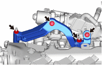
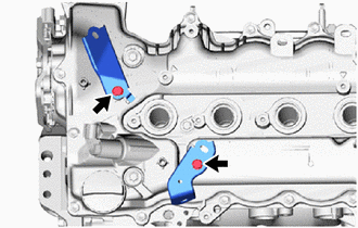
REMOVE MANIFOLD STAY
-
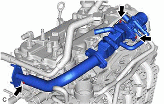
REMOVE EXHAUST MANIFOLD CONVERTER SUB-ASSEMBLY
-
REMOVE EXHAUST MANIFOLD GASKET
-
REMOVE EXHAUST COOLER ASSEMBLY
-
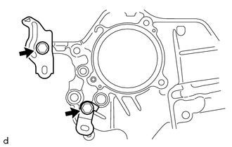
REMOVE EXHAUST MANIFOLD TO HEAD GASKET
-
REMOVE EGR PIPE GASKET
-
REMOVE VENTILATION HOSE ASSEMBLY
-
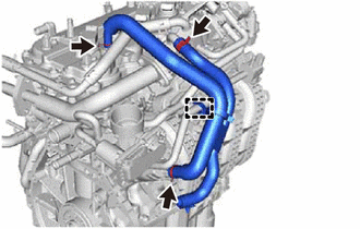
Disengage the clamp to separate the ventilation hose assembly from the hose clamp.
-
Slide the 3 hose clips and remove the ventilation hose assembly from the cylinder head cover sub-assembly, EGR cooler assembly and intake manifold.
-
-
REMOVE EGR VALVE ASSEMBLY
-
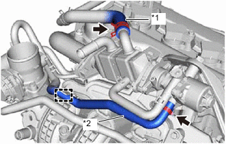
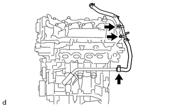
*1 No. 4 Water By-pass Hose *2 No. 2 Water By-pass Hose Slide the hose clip and disconnect the No. 4 water by-pass hose from the EGR cooler assembly.
-
Slide the hose clip and disconnect the No. 2 water by-pass hose from the EGR valve assembly.
-
Disengage the clamp to separate the No. 2 water by-pass hose from the hose clamp.
-
Remove the 2 bolts, 2 nuts and EGR valve bracket from the EGR valve assembly, EGR cooler assembly, camshaft housing sub-assembly and timing chain cover assembly.
-
Remove the bolt, 2 nuts and EGR valve assembly together with the EGR cooler assembly and EGR pipe assembly from the intake manifold and cylinder head sub-assembly.
-
-
REMOVE EGR INLET GASKET
-
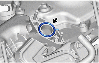
Remove the EGR inlet gasket from the intake manifold.
-
-
REMOVE PURGE VALVE (PURGE VSV)
-
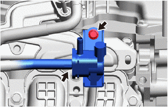
Disconnect the No. 2 fuel vapor feed hose from the purge valve (purge VSV).
-
Remove the bolt and purge valve (purge VSV).
-
-
REMOVE INTAKE MANIFOLD
-
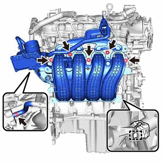
Disengage the clamp to separate the No. 4 engine wire connector from the intake manifold.
-
Slide the hose clip and disconnect the water by-pass hose from the cylinder head sub-assembly.
-
Remove the 3 bolts, 2 nuts and intake manifold from the cylinder head sub-assembly.
-
-
REMOVE NO. 1 INTAKE MANIFOLD TO HEAD GASKET
-
REMOVE NO. 6 ENGINE WIRE
-
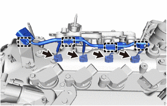
Disconnect the 4 fuel injector assembly connectors.
-
Disengage the 4 clamps to remove the No. 6 engine wire from the wire harness clamp bracket and cylinder head cover sub-assembly.
-
-
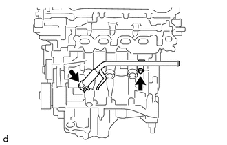
REMOVE NO. 2 WATER BY-PASS PIPE
-
Slide the hose clip and disconnect the No. 6 water by-pass hose from the No. 1 water by-pass pipe.
-
Remove the bolt, nut, wire harness clamp bracket and No. 2 water by-pass pipe from the cylinder head cover sub-assembly.
-
-
REMOVE NO. 1 WATER BY-PASS PIPE
-
Slide the hose clip and disconnect the No. 1 water by-pass hose from the water inlet with thermostat sub-assembly.
-
Remove the bolt and No. 1 water by-pass pipe from the cylinder block sub-assembly.
-
-
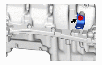
REMOVE V-RIBBED BELT TENSIONER ASSEMBLY
-
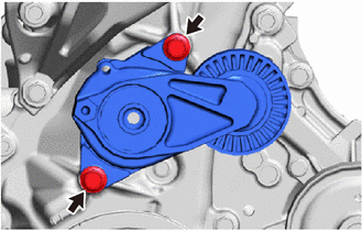
Remove the 2 bolts and V-ribbed belt tensioner assembly from the timing chain cover assembly.
-
-
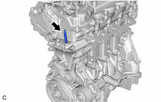
REMOVE NO. 1 IGNITION COIL
-
REMOVE NO. 4 ENGINE WIRE
-
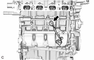
Disconnect the knock sensor connector to remove the No. 4 engine wire.
-
-
REMOVE WIRE HARNESS CLAMP BRACKET
-
Remove the 2 bolts and 2 wire harness clamp brackets from the cylinder head cover sub-assembly.
-
Remove the bolt and wire harness clamp bracket from the cylinder block sub-assembly.
-
Remove the 2 bolts and 2 wire harness clamp brackets from the timing chain cover assembly.
-
-
REMOVE STUD BOLT
-
Using an E8 "TORX" socket wrench, remove the stud bolt from the timing chain cover assembly.
-