ENGINE ASSEMBLY REMOVAL

CAUTION / NOTICE / HINT
CAUTION:
The engine assembly with transaxle is very heavy. Be sure to follow the procedure described in the repair manual, or the engine lifter may suddenly drop.
PROCEDURE
-
PRECAUTION
Note
After turning the ignition switch off, waiting time may be required before disconnecting the cable from the negative (-) battery terminal. Therefore, make sure to read the disconnecting the cable from the negative (-) battery terminal notices before proceeding with work.
-
DISCHARGE FUEL SYSTEM PRESSURE
-
DISCONNECT CABLE FROM NEGATIVE BATTERY TERMINAL
Note
When disconnecting the cable, some systems need to be initialized after the cable is reconnected.
-
ALIGN FRONT WHEELS FACING STRAIGHT AHEAD
-
SECURE STEERING WHEEL SUB-ASSEMBLY
-
REMOVE FRONT WHEELS
-
REMOVE ENGINE UNDER COVER LH
-
Remove the 3 bolts, 3 screws and engine under cover LH from the vehicle.
-
-
REMOVE ENGINE UNDER COVER RH
-
Remove the 2 bolts, screw and engine under cover RH from the vehicle.
-
-
DRAIN ENGINE COOLANT
-
DRAIN CONTINUOUSLY VARIABLE TRANSAXLE FLUID (for CVT)
-
DRAIN MANUAL TRANSAXLE OIL (for Manual Transaxle)
-
DRAIN ENGINE OIL
-
REMOVE FRONT FLOOR CENTER BRACE
-
REMOVE FRONT EXHAUST PIPE ASSEMBLY
-
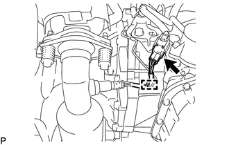
Disconnect the heated oxygen sensor connector.
-
Disengage the clamp to separate the heated oxygen sensor wire from the wire harness clamp bracket.
-
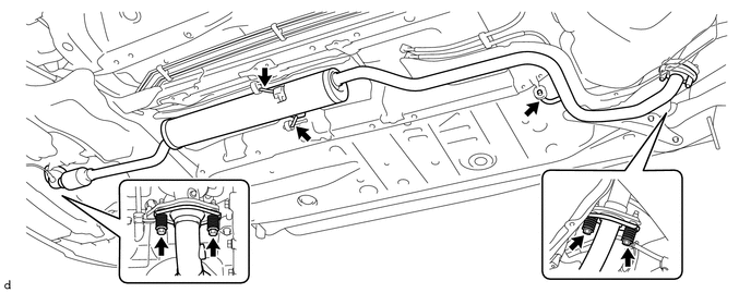
Remove the 2 bolts and 2 compression springs to separate the front exhaust pipe assembly from the tail exhaust pipe assembly.
-
Remove the 2 bolts and 2 compression springs to separate the front exhaust pipe assembly from the exhaust manifold converter sub-assembly.
-
Disconnect the 3 exhaust pipe supports to remove the front exhaust pipe assembly.
-
Remove the 2 exhaust pipe gaskets from the exhaust manifold converter sub-assembly and front exhaust pipe assembly.
-
-
REMOVE FRONT DRIVE SHAFT ASSEMBLY
-
REMOVE WINDSHIELD WIPER MOTOR AND LINK
-
REMOVE FRONT AIR SHUTTER SEAL RH
-
for LHD:
-
for RHD:
-
-
REMOVE FRONT NO. 1 VENTILATOR SEAL
-
for LHD:
-
for RHD:
-
-
REMOVE INNER COWL TOP TO COWL BRACE
-
for LHD:
-
for RHD:
-
-
REMOVE OUTER COWL TOP PANEL
-
for LHD:
-
for RHD:
-
-
REMOVE NO. 1 ENGINE COVER
-
DISCONNECT NO. 2 VENTILATION HOSE
-
SEPARATE NO. 2 VACUUM SWITCHING VALVE ASSEMBLY (for CVT)
-
DISCONNECT NO. 1 AIR HOSE (for CVT)
-
REMOVE AIR CLEANER HOSE ASSEMBLY
-
REMOVE AIR CLEANER CAP SUB-ASSEMBLY
-
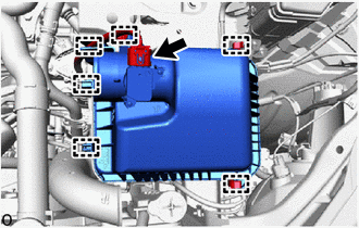
Disconnect the mass air flow meter connector.
-
Disengage the 2 clamps to separate the engine wire from the air cleaner cap sub-assembly.
-
Disengage the 2 clamps of the air cleaner cap sub-assembly.
-
Disengage the 2 guides to remove the air cleaner cap sub-assembly from the air cleaner case sub-assembly.
-
-
REMOVE AIR CLEANER FILTER ELEMENT SUB-ASSEMBLY
-
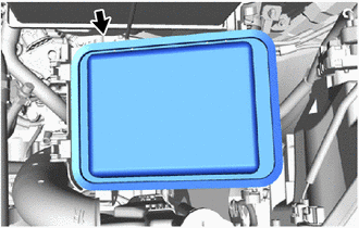
Remove the air cleaner filter element sub-assembly from the air cleaner case sub-assembly.
-
-
REMOVE AIR CLEANER CASE SUB-ASSEMBLY
-
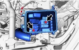
Disengage the clamp to separate the engine wire from the air cleaner case sub-assembly.
-
Remove the 2 bolts and air cleaner case sub-assembly from the air cleaner bracket.
-
-
REMOVE BATTERY
-
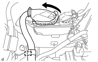
Open the fusible link cover.
-
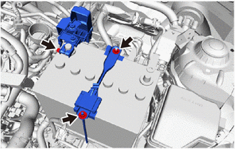
Loosen the nut and disconnect the cable from the positive (+) battery terminal.
-
Remove the 2 nuts, battery clamp bolt and battery clamp sub-assembly from the battery carrier.
-
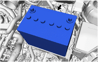
Remove the battery from the battery tray.
-
-
REMOVE BATTERY TRAY
-
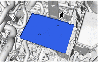
Remove the battery tray from the battery carrier.
-
-
REMOVE BATTERY CARRIER
-
Disengage the 4 clamps to separate the engine wire from the battery carrier.
-
Remove the 5 bolts and battery carrier from the vehicle.
-
-
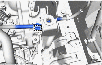
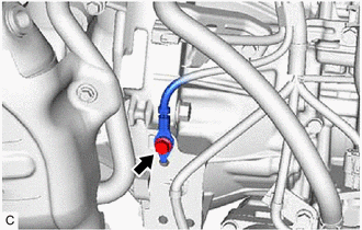
DISCONNECT FUEL VAPOR FEED HOSE ASSEMBLY
-
Slide the hose clip and disconnect the fuel vapor feed hose assembly from the purge valve (purge VSV).
-
Disengage the clamp to separate the hose clamp from the No. 3 water by-pass hose.
-
-
DISCONNECT UNION TO CONNECTOR TUBE HOSE
-
REMOVE FAN AND GENERATOR V BELT
-
REMOVE OIL LEVEL DIPSTICK SUB-ASSEMBLY
-
REMOVE OIL LEVEL DIPSTICK GUIDE
-
REMOVE OIL LEVEL DIPSTICK GUIDE O-RING
-
REMOVE NO. 1 EXHAUST MANIFOLD HEAT INSULATOR
-
REMOVE GENERATOR ASSEMBLY
-
for DENSO Made:
-
for VALEO Made:
-
-
DISCONNECT NO. 1 RADIATOR HOSE
-
Slide the hose clip and disconnect the No. 1 radiator hose from the cylinder head sub-assembly.
-
-
DISCONNECT NO. 2 RADIATOR HOSE
-
Slide the hose clip and disconnect the No. 2 radiator hose from the water inlet with thermostat sub-assembly.
-
-
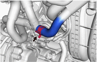
DISCONNECT OUTLET HEATER WATER HOSE A
-
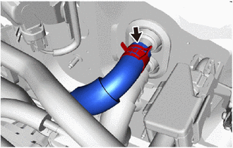
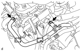
Slide the hose clip and disconnect the outlet heater water hose A from the heater radiator assembly.
Note
-
Do not apply excessive force to the water hose and outlet heater water hose A.
-
Prepare a drain pan or cloth in case the coolant leaks.
-
-
-
DISCONNECT INLET HEATER WATER HOSE A
-
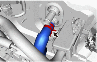
Slide the hose clip and disconnect the inlet heater water hose A from the heater radiator assembly.
Note
-
Do not apply excessive force to the water hose and inlet heater water hose A.
-
Prepare a drain pan or cloth in case the coolant leaks.
-
-
-
REMOVE NO. 2 EFI FUEL PIPE CLAMP
-
DISCONNECT FUEL TUBE SUB-ASSEMBLY
-
DISCONNECT TRANSMISSION CONTROL CABLE ASSEMBLY (for CVT)
-
DISCONNECT TRANSMISSION CONTROL CABLE ASSEMBLY (for Manual Transaxle)
-
SEPARATE CLUTCH HOSE (for Manual Transaxle)
-
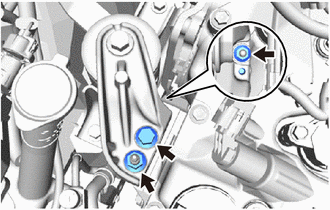
SEPARATE COMPRESSOR WITH PULLEY ASSEMBLY (w/ Air Conditioning System)
-
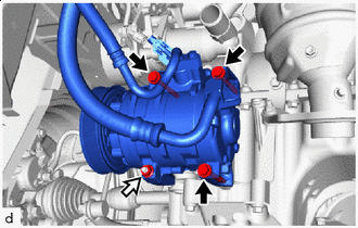

Bolt 
Nut Remove the 3 bolts and nut.
-
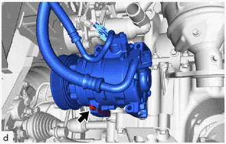
Using an E8 "TORX" socket wrench, remove the stud bolt and separate the compressor with pulley assembly from the cylinder block sub-assembly and oil pan sub-assembly.
Note
Separate the compressor with pulley assembly together with the suction hose sub-assembly and discharge hose sub-assembly, then suspend them from the vehicle with a piece of rope.
-
-
SEPARATE ENGINE WIRE (for LHD)
-
Disengage the clamp to separate the engine wire from the air cleaner bracket.
-
Disengage the clamp.
-
Lift up the lever to disengage the lock, and disconnect the ECM connector from the ECM.
Note
When disconnecting connectors, make sure that foreign substances such as mud or water droplets do not adhere to them.
-
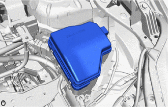
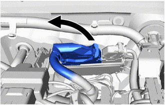
Remove the relay block cover from the engine room relay block.
-
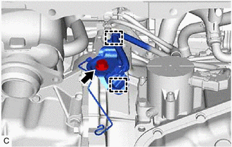
Remove the bolt to separate the engine wire from the vehicle.
-
Disengage the clamp to separate the engine wire from the vehicle.
-
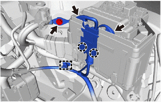
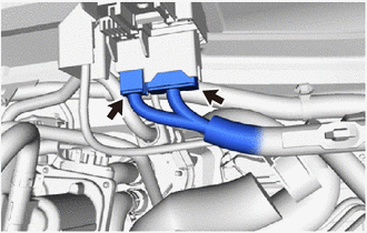
Disconnect the 2 connectors from the engine room relay block.
-
Disengage the 2 claws to separate the engine wire from the engine room relay block.
-
Disconnect the 2 connectors of the positive (+) battery terminal.
-
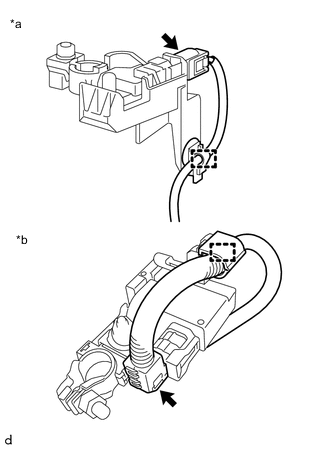
*a w/ Stop and Start System *b w/o Stop and Start System Disconnect the battery state sensor assembly connector.
-
Disengage the clamp to separate the engine wire from the battery current sensor holder.
-
-
SEPARATE ENGINE WIRE (for RHD)
-
Disengage the clamp to separate the engine wire from the air cleaner bracket.
-
Lift up the lever to disengage the lock, and disconnect the ECM connector from the ECM.
Note
When disconnecting connectors, make sure that foreign substances such as mud or water droplets do not adhere to them.
-
Remove the relay block cover from the engine room relay block.
-
Remove the bolt to separate the engine wire from the vehicle.
-
Disengage the clamp to separate the engine wire from the vehicle.
-
Disconnect the 2 connectors from the engine room relay block.
-
Disengage the 2 claws to separate the engine wire from the engine room relay block.
-
Disconnect the 2 connectors of the positive (+) battery terminal.
-
*a w/ Stop and Start System *b w/o Stop and Start System Disconnect the battery state sensor assembly connector.
-
Disengage the clamp to separate the engine wire from the battery current sensor holder.
-
-
REMOVE COLUMN HOLE COVER SILENCER SHEET
-
SEPARATE STEERING SLIDING YOKE SUB-ASSEMBLY
-
SEPARATE NO. 1 STEERING COLUMN HOLE COVER SUB-ASSEMBLY
-
REMOVE WIRE HARNESS CLAMP BRACKET
-
Disengage the 2 clamps to separate the engine wire from the wire harness clamp bracket.
-
Remove the bolt and wire harness clamp bracket from the transaxle assembly.
-
-
REMOVE ENGINE WITH TRANSAXLE ASSEMBLY
-
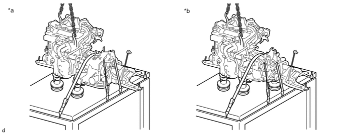
Place height adjustment attachments and plate lift attachments in the positions shown in the illustration and set an engine lifter underneath the engine with transaxle assembly and front suspension crossmember sub-assembly.
Note
-
Keep the engine with transaxle assembly and front crossmember sub-assembly horizontal.
-
Do not perform any procedures while the engine assembly is suspended because doing so may cause the engine assembly to drop, resulting in injury. However, the engine assembly needs to be suspended when it is installed to or removed from an engine stand.
-
To prevent the oil pan sub-assembly from deforming, do not place any attachments under the oil pan sub-assembly of the continuously variable transaxle assembly (for CVT).
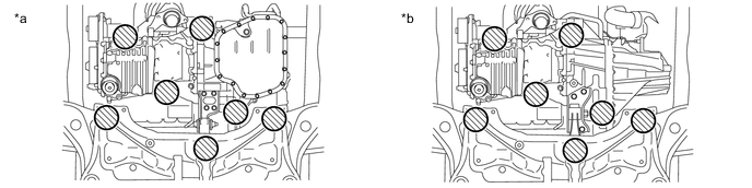
*a for CVT *b for Manual Transaxle 
Attachment Installation Positions - - -
-
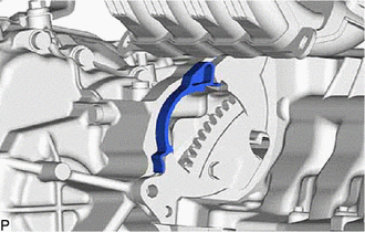
Remove the bolt, 2 nuts and then separate the engine mounting insulator sub-assembly RH from the timing chain cover assembly.
-
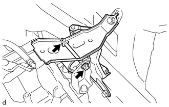
Remove the through bolt and nut, and then separate the engine mounting insulator LH from the engine mounting bracket LH.
Tech Tips
Loosen by holding the nut and turning the through bolt.
-
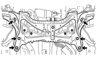
Remove the 6 bolts.
-
Operate the engine lifter and remove the engine with transaxle assembly and front suspension crossmember sub-assembly from the vehicle.
Note
When removing the engine with transaxle assembly and front suspension crossmember sub-assembly, be careful not to damage any engine wire or the steering shaft.
-
-
INSTALL ENGINE HANGER
-
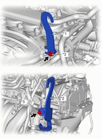
*1 No. 1 Engine Hanger *2 No. 2 Engine Hanger *3 Bolt Install the No. 1 engine hanger and No. 2 engine hanger to the cylinder head sub-assembly with the 2 bolts.
- Torque:
- 43 N*m { 438 kgf*cm, 32 ft.*lbf }
Tech Tips
Part Name Part No. No. 1 engine hanger 12281-47023 No. 2 engine hanger 12282-47010 Bolt 91552-81040
-
-
SECURE ENGINE WITH TRANSAXLE ASSEMBLY
-
Attach an engine sling device to the engine hangers and chain block.
-
To enable removal of the engine assembly, adjust the positions of the height adjustment attachments and plate lift attachments and set them in place.
Note
-
Keep the engine with transaxle assembly and front crossmember sub-assembly horizontal.
-
Do not perform any procedures while the engine assembly is suspended because doing so may cause the engine assembly to drop, resulting in injury. However, the engine assembly needs to be suspended when it is installed to or removed from an engine stand.
-
To prevent the oil pan sub-assembly from deforming, do not place any attachments under the oil pan sub-assembly of the continuously variable transaxle assembly (for CVT).
-
-
Using a rope or belt, secure the engine with transaxle assembly and front suspension crossmember sub-assembly to the engine lifter.
*a for CVT *b for Manual Transaxle Note
-
Do not tighten the rope or belt with a tightening mechanism any more than necessary.
-
Keep the engine with transaxle assembly and front crossmember sub-assembly horizontal.
-
Pay attention to the angle of the engine sling device as the engine assembly or engine hanger may be damaged or deformed if the angle is incorrect.
-
-
-
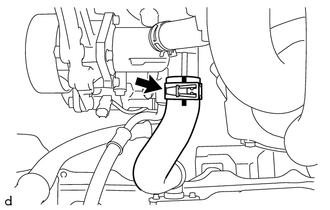
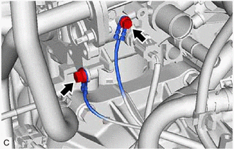
DISCONNECT INLET HEATER WATER HOSE A (for CVT)
-
Disengage the 2 clamps.
-
Slide the 2 hose clips and disconnect the inlet heater water hose A from the cylinder head sub-assembly and exhaust cooler assembly.
-
-
REMOVE INLET HEATER WATER HOSE A (for Manual Transaxle)
-
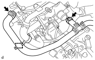
Disengage the clamp.
-
Slide the 2 hose clips and disconnect the inlet heater water hose A from the cylinder head sub-assembly and exhaust cooler assembly.
-
-
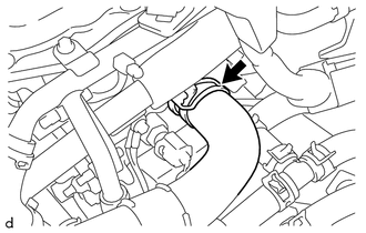
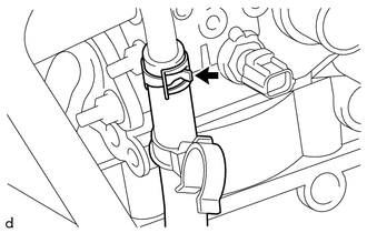
DISCONNECT VENTILATION HOSE ASSEMBLY
-
Slide the hose clip and disconnect the ventilation hose assembly from the heater water pipe.
-
-
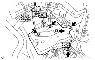
REMOVE ENGINE WIRE
-
Remove the bolt to separate the engine wire from the transaxle assembly.
-
Remove the 2 bolts to separate the engine wire from the cylinder head sub-assembly.
-
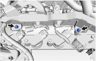
Remove the 2 nuts to separate the engine wire from the cylinder head cover sub-assembly.
-
Disconnect all of the connectors and wire harness clamps and remove the engine wire from the engine assembly.
-
-
REMOVE STARTER ASSEMBLY
-
REMOVE FLYWHEEL HOUSING SIDE COVER
-
Remove the flywheel housing side cover from the cylinder block sub-assembly.
-
-
REMOVE DRIVE PLATE AND TORQUE CONVERTER ASSEMBLY SETTING BOLT (for CVT)
-
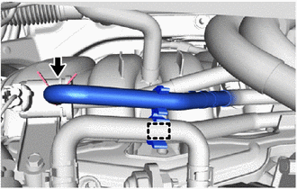
DISCONNECT WATER INLET HOSE (for CVT)
-
Slide the hose clip and disconnect the water inlet hose from the No. 2 water by-pass pipe.
-
-
REMOVE CONTINUOUSLY VARIABLE TRANSAXLE ASSEMBLY (for CVT)
-
REMOVE MANUAL TRANSAXLE ASSEMBLY (for Manual Transaxle)
-
REMOVE CLUTCH DISC ASSEMBLY (for Manual Transaxle)
-
REMOVE DRIVE PLATE AND RING GEAR SUB-ASSEMBLY (for CVT)
-
REMOVE FLYWHEEL SUB-ASSEMBLY (for Manual Transaxle)
-
INSTALL ENGINE STAND
-
Install the engine assembly to an engine stand.
Note
-
Pay attention to the angle of the engine sling device as the engine assembly or engine hanger may be damaged or deformed if the angle is incorrect.
-
Do not perform any procedure while the engine assembly is suspended because doing so may cause the engine assembly to drop, resulting in injury. However, the engine assembly needs to be suspended when it is installed to or removed from an engine stand.
-
-
-
REMOVE ENGINE HANGER
-
Remove the 2 bolts, No. 1 engine hanger and No. 2 engine hanger from the cylinder head sub-assembly.
-
-
REMOVE ENGINE MOUNTING INSULATOR SUB-ASSEMBLY RH
Tech Tips
Perform this procedure only when replacement of the engine mounting insulator sub-assembly RH is necessary.
-
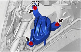
Remove the 3 bolts.
-
Disengage the hook and remove the engine mounting insulator sub-assembly RH from the vehicle.
-
-
REMOVE ENGINE MOUNTING INSULATOR LH
Tech Tips
Perform this procedure only when replacement of the engine mounting insulator LH is necessary.
-
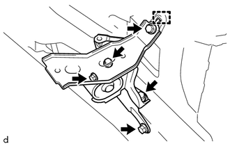
Remove the 5 bolts.
-
Disengage the hook and remove the engine mounting insulator LH from the vehicle.
-