ECD SYSTEM(w/ DPF) Lack of Power or Hesitation
DESCRIPTION
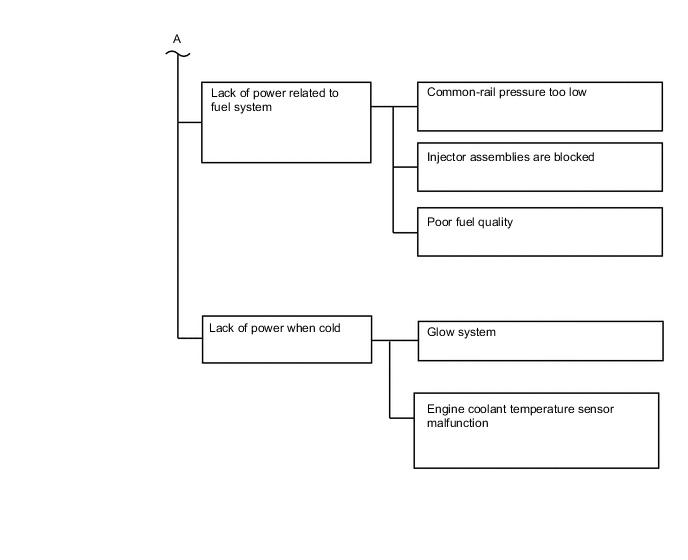
| Malfunction Condition | Main Trouble Area | Related Trouble Area |
|---|---|---|
|
|
|
Tech Tips
-
Specified values in the following troubleshooting flowchart are for reference only. Variations in the Data List values may occur depending on the measuring conditions or the vehicle age. Do not judge the vehicle to be normal even when the Data List values indicate a standard level. There are possibly some concealed factors of the malfunction.
-
Check that the vehicle has not been modified in any way prior to the vehicle inspection.
-
This troubleshooting procedure checks for the cause of an obvious lack of engine power (e.g. the vehicle speed does not reach the target speed in the high speed range) while the vehicle is being driven.
-
Faults and Symptoms of Common Rail Diesel Components
-
Engine Control
Mass Air Flow Meter Component Mass air flow meter Main fault Decrease in performance (foreign matter is stuck) Symptoms Lack of power, black smoke Data List MAF Tech Tips
The maximum fuel injection volume is controlled according to the output from the mass air flow meter.
Intake System Component Intake system Symptom: Main fault
-
Lack of power (No black smoke): air filter blockage, Air duct is crushed/leaking
-
Black smoke (No lack of power): Leakage between the turbo and intake manifold
Data List
-
MAP (intake manifold absolute pressure)
-
Target Booster Pressure
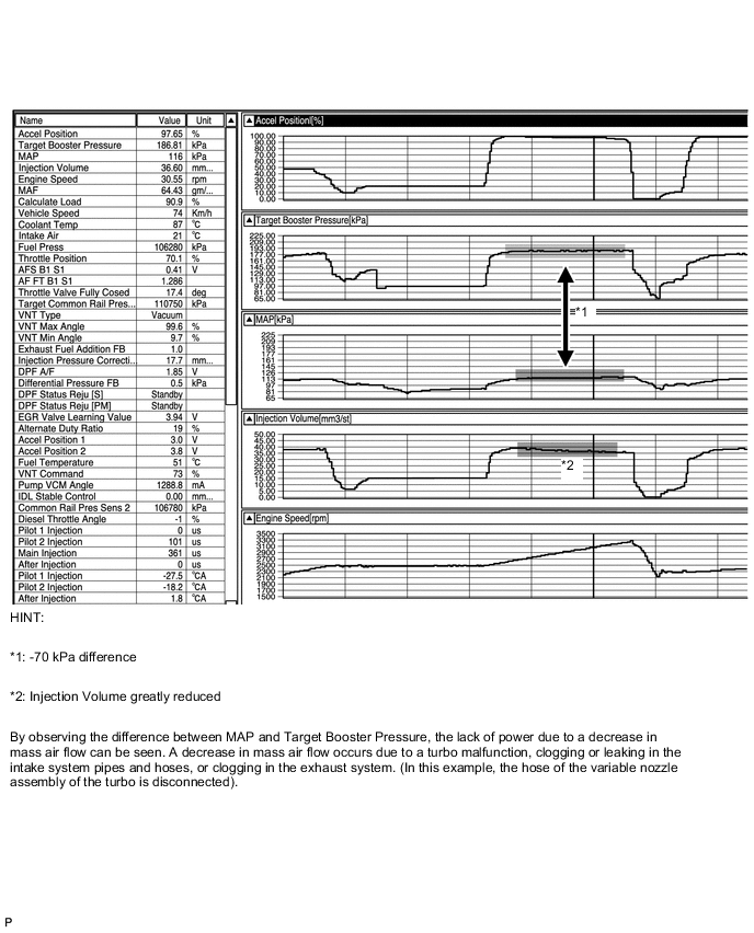
When the accelerator is fully depressed, if MAP is 15 kPa lower than Target Booster Pressure for more than 5 seconds then a lack of power will be felt.
Turbocharger System Component Turbocharger system Main fault
-
Air leak in the turbocharged air passage
-
Turbo motor driver not operating well
-
Turbocharger (turbine, bearing)
Symptoms
-
Lack of power (when vehicle starting, when vehicle under heavy load)
-
(Black smoke is not emitted when racing while vehicle stopped)
Data List MAP (intake manifold absolute pressure), Target Booster Pressure
-
When the accelerator is fully depressed, if MAP is 15 kPa lower than Target Booster Pressure for more than 5 seconds then a lack of power will be felt.
-
With the ignition switch ON or during idling, MAP = atmospheric pressure (standard atmospheric pressure = 101 kPa). When the engine speed is about 1500 rpm or more, the turbocharger starts to take effect and MAP becomes higher than atmospheric pressure.
-
Atmospheric pressure increases 1 kPa each time altitude increases by 100 m, and is also affected by the current weather conditions.
VN Turbo Command
-
0%: Vanes fully open (drive rod contracts)
-
Over 90%: Vanes fully closed (drive rod expands and turbo operates effectively)
Diagnostic Point
-
Using the Active Test "Test the Turbo Charger Step Motor", check the drive rod movement.
-
Check the drive rod movement when the ignition switch is turned from ON to off.
Exhaust System Component Exhaust system Main fault Blockage Symptoms Lack of power (high engine speed, when vehicle under heavy load) Data List MAP (intake manifold absolute pressure)
When the accelerator is fully depressed, if MAP is 15 kPa lower than Target Booster Pressure for more than 5 seconds then a lack of power will be felt.
Glow System Component Glow system Main fault Open circuit, glow plug relay fault Symptoms Difficult to start, rough idle, knocking, white smoke (when cold) Data List Check the glow plug indicator light Diagnostic Point Try to measure the resistance of the glow plug Engine - 1 Component Engine Main fault Damaged, seized up Symptoms Cannot crank, crank speed is low, strange noise Engine - 2 Component Engine Main fault Loss of compression Symptoms Rough idle (lack of power always) Data List Engine Speed of Cyl
-
The engine is cranked for approximately 10 seconds, then the speed of each cylinder is measured (compression test).
-
Indicates the speed of each cylinder when cranking. Example - Normal: Engine speed of all cylinders is approximately equal. When No. 1 cylinder compression is extremely low, "Engine speed of Cyl #1" is approximately 300 rpm, and "Engine speed of Cyl #2 to #4" is approximately 200 rpm.
-
Usually the tester displays the value of when the engine is started.
Injection Feedback Val
-
"Injection Feedback Val" more than 2.0 mm3/st: Injector assembly breakdown is causing injection volume deviation, or insufficient compression is causing poor combustion.
-
-
Diesel Injection
Fuel Supply Pump Component Supply pump assembly Main fault - Symptoms Difficult to start, engine stalling, rough idle, lack of power Data List Fuel Press, Target Common Rail Pressure, Target Pump SCV Current
-
When in a stable condition such as when idling, the fuel pressure is within +/-10000 kPa of the target fuel pressure.
-
If the fuel pressure is 20000 kPa below the target pressure then a lack of power will be felt.
-
If the fuel pressure is below 25000 kPa then idling will be rough.
Tech Tips
-
The fuel pressure changes at engine starting, but is approx. 25000 kPa at engine start after the engine is warmed up.
-
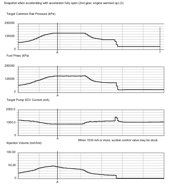
When Target Pump SCV Current is 1530 mA or more, the suction control valve has a tendency to become stuck.
Diagnostic Trouble Code Even if Fuel Press is less than Target Common Rail Pressure, a DTC may not be stored. Fuel Filter Component Fuel filter Main fault Blockage Symptoms Difficult to start, engine stalling, rough idle, lack of power Data List Fuel Press, Target Common Rail Pressure
-
When in a stable condition such as when idling, the fuel pressure is within +/-10000 kPa of the target fuel pressure.
-
If the fuel pressure is 20000 kPa below the target pressure then a lack of power will be felt.
-
If the fuel pressure is below 25000 kPa then idling will be rough.
Tech Tips
The fuel pressure changes at engine starting, but is approx. 25000 kPa at engine start after the engine is warmed up.
Diagnostic Trouble Code Even if Fuel Press is less than Target Common Rail Pressure, a DTC may not be stored. Injector Assembly Component Injector assembly Main fault Injection hole blockage
Nozzle needle or valve piston does not move smoothly
Symptoms Rough idle, lack of power, black smoke, white smoke, knocking Data List Injection Feedback Val
-
"Injection Feedback Val" more than 2.0 mm3/st: Injector assembly breakdown is causing injection volume deviation, or insufficient compression is causing poor combustion.
Pressure Control Valve Component Pressure control valve (common rail assembly) Main fault Does not completely close Symptoms Difficult to start, engine stall, rough idle, lack of power Fuel Pressure Sensor Component Fuel pressure sensor (common rail assembly) Main fault Open circuit, decrease in performance (foreign matter is stuck) Symptoms Difficult to start, rough idle, engine stall, lack of power Data List Fuel Press, Target Common Rail Pressure
-
Slowly raise the engine speed from idling to 3000 rpm with the vehicle stopped, and check that Fuel Press follows Target Common Rail Pressure. If the fuel pressure sensor malfunctions, the actual fuel pressure may deviate from the target fuel pressure. (However, the value may not deviate even when a malfunction is present).
Diagnostic Trouble Code When the fuel pressure sensor has a fault, some DTCs may be stored. Irregular Fuel Component Irregular fuel Main fault - Symptoms Difficult to start, rough idle (especially when cold) -
-
Diesel EGR
EGR System Component EGR system Main fault
-
Does not move smoothly
-
Does not close completely
Symptoms
-
Rough idle
-
EGR valve stuck closed: A loud turbocharger sound.
-
EGR valve stuck open: Difficult to start (does not stall), black smoke, lack of power (if there is an excess in the quantity of EGR and there is a heavy load, when the vehicle starts moving, a lack of power will be felt).
Data List Actual EGR Valve Pos., Target EGR Pos.
-
Generally, Actual EGR Valve Pos. = Target EGR Pos. +/-5% (fully closed 0%, fully open 100%).
-
Using EGR valve Active Test, check whether Actual EGR Valve Pos. follows Target EGR Pos. (the engine coolant temperature and intake air temperature should be considered when a malfunction occurs).
-
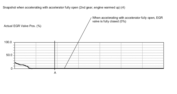
EGR valve is fully closed when the ignition switch is turned to ON (engine stopped).
-
EGR valve opens to the halfway point at idling after the engine warmed up.
-
-
Diesel Throttle
Diesel Throttle System Component Diesel throttle system Main fault Stuck, does not move smoothly Symptoms
-
Stuck closed: Lack of power, difficult to start, rough idle, engine stall, black smoke. These may occur when stuck almost fully closed.
-
Stuck open: Turbocharger sound increases. When the engine is stopped, engine vibrations may occur.
Data List
-
Actual Throttle Position, Target Throttle Position
0%: Fully open
100%: Fully closed
-
If there is a malfunction of the throttle actuator, compare the target and actual throttle position values for the troubleshooting.
-
-
-
Data List Related to Lack of Power
Tech Tips
The Data List values in the table are the results of checking one vehicle under a specific condition (engine coolant temperature, intake air temperature, atmospheric pressure etc.). Therefore, use these values for reference only.
-
Engine Control
Engine Speed Data List Judgment of Data List Values Faulty Component Diagnosis Note Engine Speed Idling: 720 to 820 rpm
-
Crankshaft position sensor
-
Crankshaft position sensor circuit
When the crankshaft position sensor is malfunctioning, "Engine Speed" is approximately 0 or varies greatly from the actual engine speed. MAP Data List Judgment of Data List Values Faulty Component Diagnosis Note MAP
-
When MAP is low, there will be difficulty starting.
-
With ignition switch ON or during idling, MAP is nearly equal to Atmosphere Pressure (standard atmospheric pressure = 101 kPa).
When MAP is low, the following conditions are possible:
-
Diesel throttle nearly fully closed.
-
Intake system blocked (turbocharger system also).
-
Exhaust system blocked.
-
When the ignition switch is ON or the vehicle is idling, MAP (intake manifold absolute pressure) and Atmosphere Pressure are approximately equal (standard atmospheric pressure = 101 kPa).
Above approx. 1500 rpm, the turbo becomes effective, and the pressure becomes higher than atmospheric pressure.
-
Inspect while comparing with "Target Booster Pressure".
-
With the accelerator fully open, if the MAP (intake manifold absolute pressure) is low compared to the target booster pressure by at least 15 kPa for 5 seconds or more, a feeling of insufficient power will occur.
Results of real-vehicle check:
-
Ignition switch ON: 99 kPa
-
Cranking: 99 kPa
-
Idling (warm up the engine): 99 kPa (2 minutes after starting the vehicle)
-
Running without load (2500 rpm): 109 kPa
-
Running without load (3000 rpm): 129 kPa
-
Running without load (4000 rpm): 164 kPa
-
Driving with the accelerator fully open at 2000 rpm: 155 kPa
-
Driving with the accelerator fully open at 3000 rpm: 220 kPa
-
Driving with the accelerator fully open at 4500 rpm: 209 kPa
MAF Data List Judgment of Data List Values Faulty Component Diagnosis Note MAF -
-
Mass air flow meter
-
Mass air flow meter circuit
-
Intake system clogging, leaking
-
Exhaust system clogging
-
Turbocharger sub-assembly
-
Leaking or clogging of turbocharger passages
-
Electric EGR control valve assembly does not close
-
Based on the MAF, the ECM controls the fuel injection volume, injection timing, EGR, etc.
-
If the value is always approximately 0 gm/sec.:
-
Mass air flow meter power source circuit is open.
-
VG circuit is open or shorted.
-
If the value is always 130 gm/sec. or more:
-
E2G circuit is open.
Results of real-vehicle check:
-
Ignition switch ON: 0 gm/sec.
-
Cranking (534 rpm): 3.27 gm/sec.
-
Idling (warm up the engine): 4.30 gm/sec. (2 minutes after starting the vehicle and "Actual EGR Valve Pos." = 65.4%)
-
Idling (warm up the engine): 8.30 gm/sec. (2 minutes after starting the vehicle and "Actual EGR Valve Pos." = 0.3%)
-
Running without load (2500 rpm): 19.97 gm/sec. (at "Actual EGR Valve Pos." = 61.9%)
-
Running without load (4000 rpm): 58.86 gm/sec.
-
Driving with the accelerator fully open at 2000 rpm: 37.22 gm/sec.
-
Driving with the accelerator fully open at 3000 rpm: 75.94 gm/sec.
-
Driving with the accelerator fully open at 4500 rpm: 92.24 gm/sec.
Tech Tips
-
The maximum fuel injection volume is controlled according to the output from the mass air flow meter.
-
If the time of engine idling is long (approximately 20 minutes or more), EGR will be cut off. At this time, if the vehicle is driven in 4th gear between 90 and 100 km/h (56 and 62 mph) for 30 minutes, EGR resumes.
Intake Air Data List Judgment of Data List Values Faulty Component Diagnosis Note Intake Air - Intake air temperature sensor
-
After a long soak, the engine coolant temperature, intake air temperature and ambient air temperature are approximately equal.
-
If the value is -40°C (-40°F) or 140°C (284°F), the sensor circuit is open or shorted.
Coolant Temp Data List Judgment of Data List Values Faulty Component Diagnosis Note Coolant Temp
-
Engine coolant temperature is approximately equal to intake air temperature after a long soak. After warm-up: Engine coolant temperature is 75°C (167°F) or more.
-
In cases when the engine coolant temperature output is obviously higher than the actual engine coolant temperature, when it is cold, there will be difficulty starting due to problems with glow plugs or insufficient fuel injection.
-
In cases when the engine coolant temperature sensor output is obviously lower than the actual engine coolant temperature, when it is warm, there will be difficulty starting (black smoke will also occur) due to an excess of injected fuel.
Engine coolant temperature sensor
-
If the value is -30°C (-22°F) or 120°C (248°F), the sensor circuit is open or shorted.
-
After a long soak, the Coolant Temp, Intake Air and ambient air temperature are approximately equal.
-
-
Diesel Injection
Target Common Rail Pressure Data List Judgment of Data List Values Faulty Component Diagnosis Note Target Common Rail Pressure - -
-
Inspect the (actual) fuel pressure, comparing it against the common rail target value.
-
Considered normal when the actual fuel pressure is within +/-10000 kPa of the target fuel pressure under stable conditions.
Results of real-vehicle check:
-
Ignition switch ON: 25000 kPa
-
Cranking: 27150 kPa
-
Idling (warm up the engine): 25000 kPa (2 minutes after starting the vehicle)
-
Running without load (2500 rpm): 43990 kPa
-
Running without load (4000 rpm): 67100 kPa
-
Driving with the accelerator fully open at 2000 rpm: 107800 kPa
-
Driving with the accelerator fully open at 3000 rpm: 155480 kPa
-
Driving with the accelerator fully open at 4500 rpm: 159640 kPa
Fuel Press Data List Judgment of Data List Values Faulty Component Diagnosis Note Fuel Press
-
Idling: 19900 to 37000 kPa 4000 rpm: 50700 to 73000 kPa Fuel Press = Target Common Rail Pressure +/-10000 kPa at stable condition
-
During cranking, if Fuel Press is lower than 25000 kPa, there may be difficulty starting (take care as there is a response lag when the pressure rises).
-
When Fuel Press is lower than 25000 kPa, rough idling will occur.
-
If there is a fault with the supply pump assembly (lack of discharge quantity) or pressure control valve (will not fully close), the fuel pressure will drop. Also, a blocked fuel filter, leakage from fuel pipes, and lack of fuel will also make the fuel pressure drop.
-
If air mixes with the fuel, the fuel pressure will shift away from the target fuel pressure.
-
When there is a fault with the supply pump assembly, there is a possibility of lack of power, engine stall, rough idle and difficulty starting.
-
Fuel pressure is the actual common rail fuel pressure.
-
Inspect by comparing the fuel pressure with the target fuel pressure.
-
When in a stable condition such as when idling, the fuel pressure is within +/-10000 kPa of the target fuel pressure.
-
The ECM uses fuel pressure for feedback control of the target fuel pressure via the supply pump. The injection amount is determined based on the injection timing and fuel pressure.
Results of real-vehicle check:
-
Ignition switch ON: 360 kPa
-
Cranking: 33570 kPa
-
Idling (warm up the engine): 24330 kPa (2 minutes after starting the vehicle)
-
Running without load (2500 rpm): 43690 kPa
-
Running without load (4000 rpm): 66340 kPa
-
Driving with the accelerator fully open at 2000 rpm: 109670 kPa
-
Driving with the accelerator fully open at 3000 rpm: 156520 kPa
-
Driving with the accelerator fully open at 4500 rpm: 160260 kPa
Target Pump SCV Current Data List Judgment of Data List Values Faulty Component Diagnosis Note Target Pump SCV Current 1530 mA or less
-
Suction control valve malfunction
-
Clogged fuel filter
-
ECM-calculated value for the suction control valve actuation target current.
-
Value is large when a high fuel pressure is desired.
-
Value becomes stuck at 1800 mA or more or operation is poor (poor movement due to deposits, etc.).
-
When this deviates from the standard value, it indicates that for some reason, even though the pump is running hard, the actual fuel pressure is inconsistent with the target fuel pressure.
Results of real-vehicle check:
-
Cranking: 1052 mA
-
Idling: 1156 mA
-
Running without load (2500 rpm): 1287 mA
-
Running without load (4000 rpm): 1217 mA
-
Driving with the accelerator fully open at 2000 rpm: 1140 mA
-
Driving with the accelerator fully open at 3000 rpm: 965 mA
-
Driving with the accelerator fully open at 4500 rpm: 954 mA
Injection Feedback Val #1 (to #4) Data List Judgment of Data List Values Faulty Component Diagnosis Note Injection Feedback Val #1 (to #4)
-
When idling after the engine is warmed up, the fuel quantity of each injector assembly is corrected to make each cylinder engine speed equal.
-
Cylinders more than 2 mm3/st may have a fault.
Tech Tips
Read the value after one minute of idling after warm up (engine coolant temperature above 75°C (167°F)). This value is only calculated when idling.
-
Injector assembly clogging
-
Injector assembly deterioration
-
Decrease in cylinder compression
-
Injector assembly compensation code is incorrectly set (forgot to input code after replacement or made mistake during setting of code after replacing ECM with one from another vehicle)
-
With injector assembly faults, other than difficulty starting, there is a possibility of rough idling, lack of power, black smoke, white smoke and knocking.
-
When idling after warm up, the injection amount for each cylinder is corrected to optimize the difference between the engine speed of each cylinder. Example: For cylinders that are slowing the engine speed compared to other cylinders, the injection volume is increased.
-
"Injection Feedback Val" more than 2.0 mm3/st: Injector assembly breakdown is causing injection volume deviation, or insufficient compression is causing poor combustion.
Injection Volume Data List Judgment of Data List Values Faulty Component Diagnosis Note Injection Volume - - If injector assemblies are clogged, fuel quality is poor, the fuel filter is clogged, or engine friction increases, then "Injection Volume" will increase. Results of real-vehicle check:
-
Cranking: 19.58 mm3/st
-
Idling (warm up the engine): 4.19 mm3/st (at "Actual EGR Valve Pos." = 0.3%)
-
Idling (warm up the engine): 4.78 mm3/st (at "Actual EGR Valve Pos." = 65.4%)
-
Running without load (2500 rpm): 4.58 mm3/st
-
Running without load (4000 rpm): 5.99 mm3/st
-
Driving with the accelerator fully open at 2000 rpm: 31.28 mm3/st
-
Driving with the accelerator fully open at 3000 rpm: 45.48 mm3/st
-
Driving with the accelerator fully open at 4500 rpm: 31.67 mm3/st
-
-
Diesel Throttle
Actual Throttle Position Data List Judgment of Data List Values Faulty Component Diagnosis Note Actual Throttle Position
-
When the ignition switch is turned to ON (engine stopped), the diesel throttle is fully open. When the ignition switch is turned from ON to off, the diesel throttle is fully closed temporarily.
-
With the diesel throttle stuck almost fully closed, there is a possibility of rough idling, engine stall, black smoke, difficulty starting and lack of power.
Diesel throttle body assembly Closing percentage of the throttle valve.
-
Fully closed: 100%
-
Fully open: 0%
If there is a malfunction of the throttle actuator, compare the target and actual throttle position values for the troubleshooting.
Results of real-vehicle check:
-
Ignition switch ON: 0%
-
Cranking: 0%
-
Idling with EGR off (warm up the engine): 0%
-
Idling with EGR on (warm up the engine): 65.4%
-
Running without load (2500 rpm): 61.9%
-
Running without load (4000 rpm): 0%
-
Driving with the accelerator fully open at 2000 rpm: 0.3%
-
Driving with the accelerator fully open at 3000 rpm: 0.3%
-
Driving with the accelerator fully open at 4500 rpm: 0%
-
-
Diesel EGR
Target EGR Position Data List Judgment of Data List Values Faulty Component Diagnosis Note Target EGR Position - -
-
Fully open: 100%
-
Fully closed: 0%
-
Used for comparison to "Actual EGR Valve Pos".
Tech Tips
If the time of engine idling is long (approximately 20 minutes or more), EGR will be cut off. At this time, if the vehicle is driven in 4th gear between 90 and 100 km/h (56 and 62 mph) for 30 minutes, EGR resumes.
Results of real-vehicle check:
-
Ignition switch ON: 0%
-
Cranking: 0%
-
Idling with EGR off (warm up the engine): 0.3%
-
Idling with EGR on (warm up the engine): 65.4%
-
Running without load (2500 rpm): 61.5%
-
Running without load (4000 rpm): 0%
-
Driving with the accelerator fully open at 2000 rpm: 0%
-
Driving with the accelerator fully open at 3000 rpm: 0%
-
Driving with the accelerator fully open at 4500 rpm: 0%
Actual EGR Valve Pos. Data List Judgment of Data List Values Faulty Component Diagnosis Note Actual EGR Valve Pos.
-
Generally Actual EGR Valve Pos. = Target EGR Position (Fully closed = 0%, Fully open = 100%)
-
The EGR valve Active Test can be used to check whether the Actual EGR Valve Pos. = Target EGR Position
Electric EGR control valve assembly
-
Fully open: 100%
-
Fully closed: 0%
-
Inspect while comparing to "Target EGR Position".
-
Check the valve movement via the Active Test.
-
Sometimes the malfunction only occurs around a certain temperature, so refer to the engine coolant temperature and outside temperature at the time the malfunction occurred.
Tech Tips
If the time of engine idling is long (approximately 20 minutes or more), EGR will be cut off. At this time, if the vehicle is driven in 4th gear between 90 and 100 km/h (56 and 62 mph) for 30 minutes, EGR resumes.
Results of real-vehicle check:
-
Ignition switch ON: 0%
-
Cranking: 0%
-
Idling with EGR off (warm up the engine): 0%
-
Idling with EGR on (warm up the engine): 65.4%
-
Running without load (2500 rpm): 61.9%
-
Running without load (4000 rpm): 0%
-
Driving with the accelerator fully open at 2000 rpm: 0.3%
-
Driving with the accelerator fully open at 3000 rpm: 0.3%
-
Driving with the accelerator fully open at 4500 rpm: 0%
-
-
-
Actual Examples of Malfunction
Tech Tips
-
The purpose of the following examples is to help you understand the relationship between each Data List item when a certain malfunction occurs. Understanding this relationship helps you find the root cause easier.
-
The following are examples of actual malfunctions of a common rail diesel engine.
-
Use them for reference when diagnosing malfunctions.
-
These are not data of YARIS 1ND-TV.
-
Lack of power caused by overly low boost pressure
-
Lack of power caused by overly low MAF
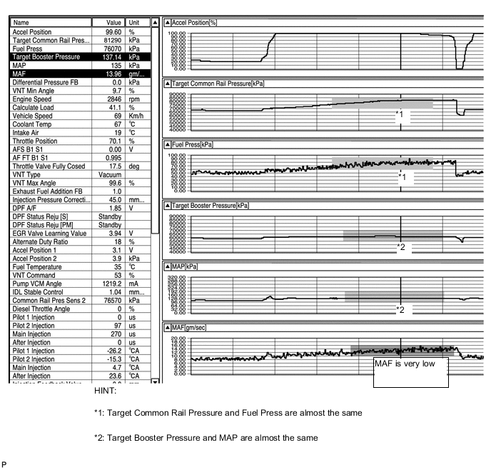
In this example, the MAF (Mass Air Flow) value decreases greatly due to foreign matter being stuck to the MAF sensor and causes a lack of power. The maximum fuel injection volume value is limited by the MAF value. As a result, there is a lack of power due to a lack of injection volume.
In this case, even when the accelerator is fully open, the calculated load is low (Calculated Load = Injection Volume / Maximum Injection Volume at Current Engine Speed).
Basically, the MAP (Manifold Absolute Pressure) is approximately equal to the Target Booster Pressure and this indicates that the turbocharger functions properly.
-
EGR valve stuck in open position
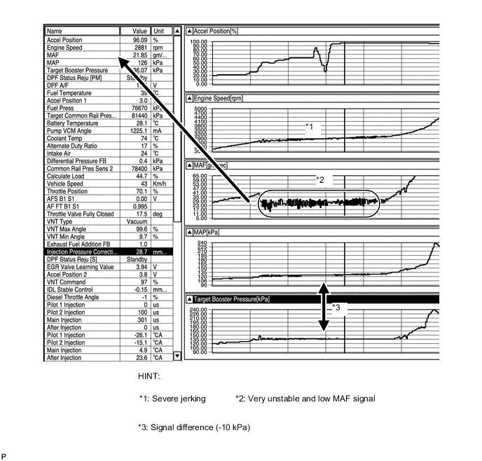
In this example, the electric EGR control valve assembly is stuck in the open position. Even with the accelerator pedal fully depressed, the EGR does not fully close and the MAF signal is low.
Therefore, the fuel injection volume becomes limited and there is a lack of power. Jerking is also evident. At this time, even while accelerating with the accelerator fully open, the calculated load is low (Calculated Load = Current Injection Volume / Maximum Injection Volume at Current Engine Speed).
Basically, the MAP (Manifold Absolute Pressure) is approximately equal to Target Booster Pressure and this indicates that the turbocharger functions properly.
-
WIRING DIAGRAM
Refer to DTC P1228 Click here.
CAUTION / NOTICE / HINT
-
Explanation of Symptom
Lack of Power The power of the diesel engine is determined by the quantity of injected fuel and the quantity of intake air.
The quantity of injected fuel is determined by the fuel pressure and the amount of time the injector assembly is open for. Basically, the fuel pressure is controlled to reach the target fuel pressure. The throttle valve does not restrict air flow volume, so the manifold absolute pressure is almost the same as atmospheric pressure when idling. At more than approximately 1500 rpm, the turbo starts to operate, causing the manifold absolute pressure to become higher than atmospheric pressure.
The manifold absolute pressure is controlled to reach the Target Booster Pressure. Also, when accelerating the vehicle at full throttle, the throttle is fully open and the EGR valve is fully closed, preserving the mass air flow.
-
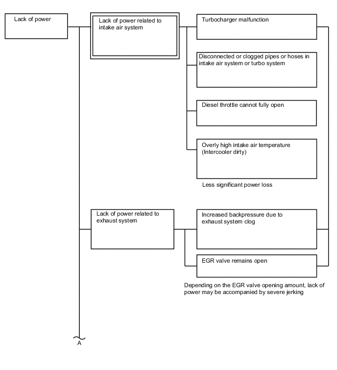
Trouble Area Chart According to Problem Cause
Note
-
When replacing the ECM, injector assembly and/or DPF catalyst, the ECM needs Registration and Initialization Click here.
-
When cleaning the electric EGR control valve assembly or diesel throttle body assembly, use a piece of cloth soaked with cleaning solvent. Spraying solvent directly onto these parts or soaking the parts in solvent may damage the parts.
Tech Tips
-
When the ECM must be replaced, before replacing the ECM, perform the "Learning Values Save" function using the intelligent tester. Then after installing the new ECM, perform all of the initialization/registrations for the "Learning Values Write" function by following the instructions shown on the tester display.
-
Before troubleshooting, conduct the following:
-
Check the fuel quality.
-
Check the fuel line for air.
-
Check the fuel system for blockages.
-
Check the air filter.
-
Check the engine oil.
-
Check the engine coolant.
-
Check the engine idling speed and maximum engine speed.
-
PROCEDURE
-
READ OUTPUT DTC (RELATED TO ENGINE)
-
Connect the intelligent tester to the DLC3.
-
Turn the ignition switch to ON and turn the tester on.
-
Enter the following menus: Powertrain / Engine and ECT / DTC / Pending.
-
Read pending DTCs.
Result Result Proceed to No DTCs are output A Engine related DTCs are output B Tech Tips
If DTC P1608 is output, proceed to step 2.
B 
GO TO DTC CHART Click here
A 
-
-
TAKE SNAPSHOT DURING LACK OF POWER
-
Connect the intelligent tester to the DLC3.
-
Start the engine and turn the tester on.
Tech Tips
The shift lever should be in neutral and the A/C switch and all accessory switches should be off.
-
Enter the following menus: Powertrain / Engine and ECT / Data List / All Data.
-
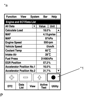
Text in Illustration *1 Snapshot Button *a Reference Take a snapshot of the following Data List items with the intelligent tester during lack of power.
CAUTION:
When performing the confirmation driving pattern, obey all speed limits and traffic laws.
Tech Tips
-
A snapshot can be used to compare vehicle data from the time of the malfunction to normal data and is very useful for troubleshooting. The data in the illustration below is that of a normal vehicle, but as the data varies between individual vehicles, this data should only be used for reference.
-
Detailed graphs can be displayed by transferring the stored snapshot data from the tester to a PC (personal computer) with Intelligent Viewer installed.
-
Move the shift lever to 2nd or 3rd gear and accelerate the vehicle with the accelerator fully open. Then, check the Data List with the engine warmed up and idling.
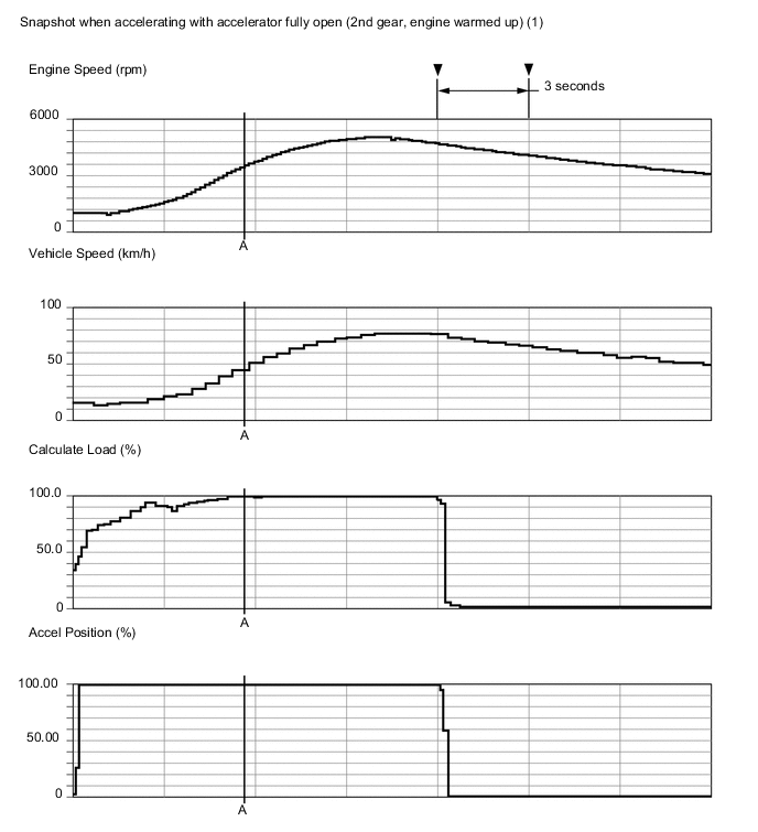
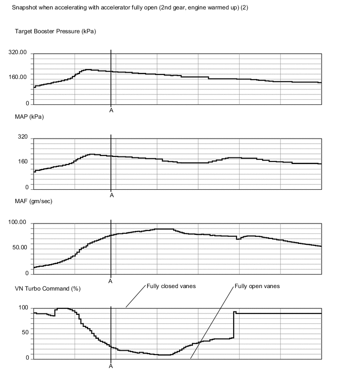
Reference Values with Engine Speed at 2000 rpm Data List Value Unit Vehicle Speed 32 km/h Engine Speed 2000 rpm Accel Position 99.60 % Target Booster Pressure 201.46 kPa MAP 155 kPa MAF 37.22 gm/sec Calculate Load 81.9 % Target Common Rail Pressure 107800 kPa Fuel Press 109670 kPa Target Pump SCV Current 1140 mA Injection Volume 31.28 mm3/st
VN Turbo Command 95 % Actual EGR Valve Pos. 0.3 % Actual Throttle Position -1 % Reference Values with Engine Speed at 3000 rpm Data List Value Unit Vehicle Speed 48 km/h Engine Speed 3000 rpm Accel Position 99.60 % Target Booster Pressure 234.25 kPa MAP 220 kPa MAF 75.49 gm/sec Calculate Load 98.8 % Target Common Rail Pressure 155480 kPa Fuel Press 156520 kPa Target Pump SCV Current 965 mA Injection Volume 45.48 mm3/st
VN Turbo Command 37 % Actual EGR Valve Pos. 0.3 % Actual Throttle Position 0 % Reference Values with Engine Speed at 3500 rpm (Point A) Data List Value Unit Vehicle Speed 58 km/h Engine Speed 3500 rpm Accel Position 99.60 % Target Booster Pressure 231.75 kPa MAP 227 kPa MAF 86.97 gm/sec Calculate Load 100.0 % Target Common Rail Pressure 158520 kPa Fuel Press 159380 kPa Target Pump SCV Current 952 mA Injection Volume 42.28 mm3/st
VN Turbo Command 29 % Actual EGR Valve Pos. 0 % Actual Throttle Position 0 % Reference Values with Engine Speed at 4000 rpm Data List Value Unit Vehicle Speed 66 km/h Engine Speed 4000 rpm Accel Position 99.60 % Target Booster Pressure 223.45 kPa MAP 219 kPa MAF 90.16 gm/sec Calculate Load 100.0 % Target Common Rail Pressure 158940 kPa Fuel Press 158720 kPa Target Pump SCV Current 947 mA Injection Volume 37.48 mm3/st
VN Turbo Command 19 % Actual EGR Valve Pos. 0 % Actual Throttle Position 0 % Data Condition Idling (Engine warmed up, A/C Off, Shift Lever in neutral) Data List Value Unit Engine Speed 798 rpm Target Booster Pressure 100.97 kPa MAP 99 kPa MAF 4.3 gm/sec Target Common Rail Pressure 25000 kPa Fuel Press 24330 kPa Target Pump SCV Current 1164 mA Injection Volume 4.58 mm3/st
VN Turbo Command 90 % Actual EGR Valve Pos. 65.4 % Actual Throttle Position 74 % Accel Position 0.00 % Target EGR Position 65.4 % Atmosphere Pressure 99 kPa Coolant Temp 75 °C Tech Tips
Actual Examples of Malfunction (See "Diagnostic Help" menu)
-
Lack of power caused by overly low boost pressure
-
Lack of power caused by overly low MAF
-
EGR valve stuck in open position
-
NEXT
-
-
CHECK SNAPSHOT
-
Check the condition of the vehicle using the snapshot taken during the lack of power.
Result Result Proceed to None of the conditions below apply A Fuel Press is less than "Target Common Rail Pressure -15000 kPa" when accelerating with accelerator fully open B Target Pump SCV Current 1530 mA or more C One of the Injection Feedback Val #1 to 4 values is outside the range of +/-2 mm3/st when idling after warm up
D Injection Feedback Val #1 to #4 is within the range of +/-2 mm3/st and Injection Volume is more than 8 mm3/st when idling after warm up
E* Tech Tips
-
*: When case "E" occurs, usually symptoms may be noticeable, such as difficult starting, rough idling, knocking or black smoke at high common rail pressure.
-
If the value of Injection Volume is more than 8 mm3/st and the value of all of the Injector Feedback Val. #1 to #4 is within the threshold, replace the injector assemblies for all cylinders.
In this case, there is a possibility that too much recirculated exhaust gas enters into the engine. Therefore, you should compare the Target EGR Position with the Actual EGR Valve Pos. by entering the following menus using the intelligent tester: Powertrain / Engine and ECT / Data List / Target EGR Position and Actual EGR Valve Pos.
If the difference between Target EGR Position and Actual EGR Valve Pos. exceeds +/-10%, the EGR system may have a malfunction.
-
B 
BLEED AIR FROM FUEL SYSTEM Click here
C
CHECK HARNESS AND CONNECTOR (SUCTION CONTROL VALVE - ECM) Click here
D
CHECK INJECTOR COMPENSATION CODE Click here
E
REPLACE INJECTOR ASSEMBLY OF ALL CYLINDERS Click here
A
-
-
CHECK SNAPSHOT
-
Check the condition of the vehicle using the snapshot taken during the lack of power.
Result Result Proceed to MAP is less than "Target Booster Pressure -15 kPa" (MAF is normal) when the engine speed is 3000 rpm or more with accelerator fully open A MAF is low when accelerating with accelerator fully open (MAP is normal)
-
3000 rpm: 61 gm/sec or less
-
3500 rpm: 67 gm/sec or less
-
4000 rpm: 70 gm/sec or less
Tech Tips
If MAF (Mass Air Flow) decreases, Calculate Load will be 80% or less when accelerating with the accelerator fully open.
B MAP and MAF are both low when accelerating with the accelerator fully open C None of the above conditions apply D -
B
INSPECT MASS AIR FLOW METER Click here
C
READ VALUE USING INTELLIGENT TESTER (ACCEL POSITION) Click here
D
READ VALUE USING INTELLIGENT TESTER (PM ACCUMULATION RATIO) Click here
A
-
-
INSPECT VACUUM HOSE
-
Check the vacuum hose connection (diesel turbo pressure sensor).
OK Vacuum hose is connected securely.
NG
REPLACE VACUUM HOSE
OK
-
-
READ VALUE USING INTELLIGENT TESTER (MAP AND ATMOSPHERE PRESSURE)
-
Connect the intelligent tester to the DLC3.
-
Turn the ignition switch to ON and turn the tester on.
-
Enter the following menus: Powertrain / Engine and ECT / Data List / MAP and Atmosphere Pressure.
-
Compare MAP to Atmosphere Pressure when the ignition switch is ON (do not start the engine).
Standard Difference between the MAP and the Atmosphere Pressure is less than 7 kPa. Tech Tips
-
If MAP and Atmosphere Pressure have the same value, both are normal. If there is a difference of 7 kPa or more, compare the values to the atmospheric pressure for that day. The sensor whose deviation is the greatest is malfunctioning.
-
Standard atmospheric pressure is 101 kPa. For every 100 m increase in altitude, pressure drops by 1 kPa. Varies by weather (high atmospheric pressure, low atmospheric pressure).
Result Result Proceed to Atmosphere Pressure is different from actual atmospheric pressure A MAP is different from actual atmospheric pressure B MAP and Atmosphere Pressure have the same value C -
A
REPLACE ECM Click here
B
REPLACE DIESEL TURBO PRESSURE SENSOR Click here
C
READ VALUE USING INTELLIGENT TESTER (ACCEL POSITION) Click here
-
-
INSPECT MASS AIR FLOW METER
-
Inspect the mass air flow meter Click here.
NG
REPLACE MASS AIR FLOW METER Click here
OK
-
-
INSPECT ELECTRIC EGR CONTROL VALVE ASSEMBLY
-
Remove the electric EGR control valve assembly.
-
Connect the electric EGR control valve assembly connector.
-
Connect the intelligent tester to the DLC3.
-
Turn the ignition switch to ON and turn the tester on.
-
Enter the following menus: Powertrain / Engine and ECT / Active Test / Control the EGR Step Position.
-
When changing the Active Test value from 0 to 100%, check that Actual EGR Valve Pos. smoothly changes to the set opening angle.
OK Value smoothly changes to the set opening angle. -
Visually check the electric EGR control valve assembly for deposits. If there are deposits, clean the electric EGR control valve assembly.
Note
-
When cleaning the electric EGR control valve assembly, make sure the valve is completely closed.
-
Do not forcibly open the valve, as it may be damaged or deformed.
-
When cleaning the electric EGR control valve assembly and the diesel throttle body assembly, use a piece of cloth with cleaning solvent. Spraying the solvent directly onto these parts or soaking the parts in the solvent may damage the parts.
-
-
Hold the electric EGR control valve assembly up to a light, and then from the side indicated by the arrow in the illustration, visually check that there is no clearance between the valve and body.
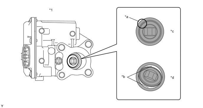
Text in Illustration *1 Electric EGR Control Valve Assembly - - *a Part A *b Clearance *c OK *d NG OK No light passes through (there is no clearance between the valve and body). If light passes through (there is a clearance between the valve and body), replace the electric EGR control valve assembly.
Tech Tips
Light passes through Part A shown in the illustration even if the valve is completely closed, this is not a problem.
-
Remove the diesel throttle body assembly, intake air connector and EGR pipe connector.
-
Remove the deposits from those parts and clean them.
Note
-
When cleaning the electric EGR control valve assembly and the diesel throttle body assembly, use a piece of cloth with cleaning solvent. Spraying the solvent directly onto these parts or soaking the parts in the solvent may damage the parts.
-
Extreme care must be taken to prevent the removed deposits from falling into the engine unit during cleaning.
Tech Tips
-
Remove the intake manifold from the cylinder head when it has to be cleaned.
-
Do not leave any deposits in the electric EGR control valve assembly when cleaning the valve.
-
NG
REPLACE ELECTRIC EGR CONTROL VALVE ASSEMBLY Click here
OK
-
-
READ VALUE USING INTELLIGENT TESTER (ACCEL POSITION)
-
Connect the intelligent tester to the DLC3.
-
Turn the ignition switch to ON and turn the tester on.
-
Enter the following menus: Powertrain / Engine and ECT / Data List / Accel Position.
-
Read the value.
Standard Condition Standard Value Accelerator pedal released 0% Accelerator pedal depressed 95% or more Accelerator pedal released → depressed 0 to 95% or more Tech Tips
*: Make sure the Accel Position opening angle changes smoothly.
NG
REPLACE ACCELERATOR PEDAL SENSOR ASSEMBLY Click here
OK
-
-
INSPECT DIESEL THROTTLE BODY ASSEMBLY
-
Inspect the diesel throttle body assembly Click here.
NG
REPLACE DIESEL THROTTLE BODY ASSEMBLY Click here
OK
-
-
CHECK INTAKE SYSTEM
-
Check for air leakage and blockage between the air cleaner and turbocharger, and between the turbocharger and intake manifold.
Tech Tips
-
Check that the intercooler is not clogged with foreign matter.
-
Check that there are no disconnected, pinched or leaking hoses or pipes.
-
Check that there are no modifications made by the user.
OK No leakage or blockage. -
NG
REPAIR OR REPLACE MALFUNCTIONING PARTS
OK
-
-
INSPECT TURBOCHARGER SUB-ASSEMBLY
-
Inspect the turbocharger sub-assembly Click here.
NG
REPLACE TURBOCHARGER SUB-ASSEMBLY Click here
OK
-
-
CONFIRM WHETHER MALFUNCTION HAS BEEN SUCCESSFULLY REPAIRED
-
Check whether the lack of power has been successfully repaired.
OK Malfunction has been repaired successfully. Tech Tips
Symptoms may have appeared due to carbon deposits, etc.
OK
END
NG
CHECK INTAKE SYSTEM DEPOSIT Click here
-
-
BLEED AIR FROM FUEL SYSTEM
-
Bleed the air from the fuel system Click here.
NEXT
-
-
CONFIRM WHETHER MALFUNCTION HAS BEEN SUCCESSFULLY REPAIRED
-
Check whether the lack of power has been successfully repaired.
Tech Tips
Fuel Press is within +/-10000 kPa of Target Common Rail Pressure.
OK Malfunction has been repaired successfully.
OK
END
NG
-
-
CHECK AND REPLACE FUEL INLET LINE
-
Check the following items, and repair or replace the malfunctioning part if necessary.
-
Check for fuel filter clogging.
-
Check for fuel freezing in the fuel line.
-
Check for clogging or leaks in the fuel pipe and hose between the fuel tank and fuel supply pump.
-
NEXT
-
-
PERFORM ACTIVE TEST USING INTELLIGENT TESTER (TEST THE FUEL LEAK)
-
Connect the intelligent tester to the DLC3.
-
Turn the ignition switch to ON and turn the tester on.
-
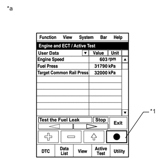
Text in Illustration *1 Snapshot Button *a Reference Enter the following menus: Powertrain / Engine and ECT/ Active Test / Test the Fuel Leak / Data List / Fuel Press, Target Common Rail Pressure and Target Pump SCV Current.
-
Take a snapshot with the tester during the Active Test.
Tech Tips
Detailed graphs can be displayed by transferring the stored snapshot data from the tester to a PC (personal computer) with Intelligent Viewer installed.
-
Maintain the engine speed of 3500 rpm, and then press the "Start" button.
-
Measure the difference between the target fuel pressure (Target Common Rail Pressure) and the actual fuel pressure (Fuel Press) when the Active Test / Test the Fuel Leak is performed.
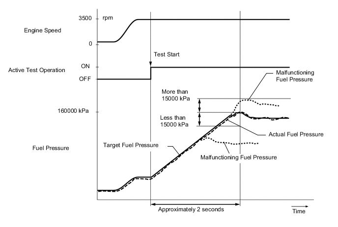
Tech Tips
-
The EPS, ABS and SRS warning lights may blink when the engine speed exceeds 3500 rpm during this test.
-
To ensure accurate measurements, perform the Active Test with measurements 5 times or more.
Standard The difference between the target fuel pressure and the actual fuel pressure is less than 15000 kPa when the target fuel pressure reaches the maximum value approximately 2 seconds after the Active Test starts. -
-
Read the value of Target Pump SCV Current in the Data List when the "Test the Fuel Leak" Active Test is performed.
Standard current Target Pump SCV Current is less than 1530 mA. Tech Tips
If the value of Target Pump SCV Current stored in the snapshot is higher than the standard, the intermittent suction control valve is probably stuck.
OK
END
NG
-
-
CHECK HARNESS AND CONNECTOR (SUCTION CONTROL VALVE - ECM)
-
Disconnect the suction control valve connector.
-
Disconnect the ECM connector.
-
Measure the resistance according to the value(s) in the table below.
Standard Resistance Tester Connection Condition Specified Condition B67-2 - B21-12 (PCV) Always Below 1 Ω B67-2 or B21-12 (PCV) - Body ground Always 10 kΩ or higher
NG
REPAIR OR REPLACE HARNESS OR CONNECTOR
OK
-
-
CHECK IF FUEL IS BEING SUPPLIED TO SUPPLY PUMP ASSEMBLY
-
Disconnect the inlet hose from the supply pump assembly.
-
Operate the priming pump and check that fuel is being supplied to the supply pump assembly.
OK Fuel is properly supplied to the supply pump assembly when the priming pump is operated. Tech Tips
-
When there is a lack of fuel, fuel pressure drops.
-
Check for fuel filter clogging.
-
Check for fuel freezing in the fuel line.
-
Check for clogging or leaks in the fuel pipe and hose between the fuel tank and supply pump assembly.
-
NG
CHECK AND REPLACE CLOGGED FUEL PIPE (INCLUDING FUEL FREEZING) (FUEL TANK - SUPPLY PUMP ASSEMBLY) Click here
OK
-
-
REPLACE SUPPLY PUMP ASSEMBLY
-
Replace the supply pump assembly Click here.
NEXT
-
-
BLEED AIR FROM FUEL SYSTEM
-
Bleed the air from the fuel system Click here.
NEXT
-
-
CONFIRM WHETHER MALFUNCTION HAS BEEN SUCCESSFULLY REPAIRED
-
Check whether the lack of power has been successfully repaired.
Tech Tips
Fuel Press is within +/-10000 kPa of Target Common Rail Pressure.
NEXT
END
-
-
READ VALUE USING INTELLIGENT TESTER (PM ACCUMULATION RATIO)
-
Drive the vehicle at a constant engine speed of 2000 rpm or more (shift position: 3rd) and a vehicle speed within 65 to 100 km/h (40 to 62 mph) for 5 minutes or more.
CAUTION:
When performing the confirmation driving pattern, obey all speed limits and traffic laws.
-
Connect the intelligent tester to the DLC3.
-
Turn the ignition switch to ON and turn the tester on.
-
Start the engine and warm it up until the engine coolant temperature reaches 75°C (167°F) or more.
-
Enter the following menus: Powertrain / Engine and ECT / Data List / PM Accumulation Ratio.
-
Check the PM Accumulation Ratio at an engine speed of 4000 rpm without load.
Tech Tips
-
When reading the values of Data List, confirm that PM regeneration is not activating (value of "After Injection Period" is 0) by entering the following menus: Powertrain / Engine and ECT / Data List / After Injection Period.
If PM regeneration is activating (value of "After Injection Period" is not 0), drive the vehicle until the PM regeneration is complete (value of "After Injection Period" becomes 0).
-
Detailed graphs can be displayed by transferring the stored snapshot data from the tester to a PC (personal computer) with Intelligent Viewer installed.
Standard PM Accumulation Rate is less than 40%. -
-
Fully depress the accelerator pedal for 5 seconds and then release it when the vehicle is stopped (A).
-
Repeat procedure A 10 times (B).
-
Check for black smoke emission during the above procedures A and B.
OK Black smoke is emitted less than 5 times. Tech Tips
Even if the black smoke is very thin, count the black smoke emission if there is any visible smoke.
Result Differential Pressure (kPa) Note Proceed to Except below - A Black smoke is emitted 5 times or more The DPF catalyst cannot trap PM because it is melted or cracked, and therefore must be replaced.
Also, if a piece of the catalyst breaks off, due to melting or another condition, and enters the exhaust pipe downstream, the exhaust pipe could be blocked, possibly causing a different malfunction.
Therefore, when replacing the DPF catalyst, visually inspect the rear surface of the DPF filter substrate to determine if replacement of the exhaust pipe is necessary.
B PM Accumulation Rate 40% or more
at 4000 rpm (No engine load)
An extremely large amount of PM (Particulate Matter) has accumulated in the DPF catalyst.
If DPF catalyst regeneration is performed in this condition, the heat generated will be excessive, possibly causing another malfunction. Therefore, replace the DPF catalyst.
C Tech Tips
-
If the PM Accumulation Rate is more than about 149% at an engine speed of 4000 rpm without load, DTC P2463 (Diesel Particulate Filter Restriction - Soot Accumulation) will be present.
-
If the Differential Pressure outputs a negative value when the engine is maintained at an engine speed of 3000 rpm with no load, the hose and pipe connections may be incorrect.
-
B
REPLACE NO. 2 EXHAUST MANIFOLD CONVERTER SUB-ASSEMBLY (DPF CATALYTIC CONVERTER) Click here
C
PERFORM ACTIVE TEST USING INTELLIGENT TESTER (FIRST TIME OF ACTIVATE THE DPF REJUVENATE (PM)) Click here
A
-
-
CHECK TEMPERATURE WHEN LACK OF POWER OCCURS
-
Check the temperature when the lack of power occurs.
Result Result Proceed to Poor acceleration only when engine is cold A Poor acceleration when engine is cold and warm B
B
CHECK INJECTOR COMPENSATION CODE Click here
A
-
-
INSPECT ENGINE COOLANT TEMPERATURE SENSOR
-
Inspect the engine coolant temperature sensor Click here.
Tech Tips
Confirm that the engine coolant temperature is 60°C or more using the intelligent tester, and then leave the vehicle overnight (7 hours or more). The actual engine coolant temperature and atmosphere temperature should be very similar.
NG
REPLACE ENGINE COOLANT TEMPERATURE SENSOR Click here
OK
-
-
CHECK PRE-HEATING CONTROL CIRCUIT
-
Check the pre-heating control circuit Click here.
NG
REPAIR OR REPLACE MALFUNCTIONING PARTS
OK
-
-
CHECK INJECTOR COMPENSATION CODE
-
Read the injector compensation codes Click here.
OK Compensation codes stored in the ECM match the compensation codes of the installed injector assemblies.
NG
PERFORM REGISTRATION AND INITIALIZATION Click here
OK
-
-
CHECK FUEL QUALITY
-
Check that fuel with a low cetane number is used.
NEXT
-
-
CONFIRM WHETHER MALFUNCTION HAS BEEN SUCCESSFULLY REPAIRED
-
Check whether the lack of power has been successfully by starting the engine.
NEXT
END
-
-
CHECK INJECTOR COMPENSATION CODE
-
Read the injector compensation codes Click here.
OK Compensation codes stored in the ECM match the compensation codes of the installed injector assemblies.
NG
PERFORM REGISTRATION AND INITIALIZATION Click here
OK
-
-
PERFORM ACTIVE TEST USING INTELLIGENT TESTER (CONTROL THE CYLINDER #1 TO #4 FUEL CUT)
Tech Tips
Use this Active Test to determine the malfunctioning cylinder.
-
Connect the intelligent tester to the DLC3.
-
Start the engine and turn the tester on.
-
Enter the following menus: Powertrain / Engine and ECT / Active Test / Control the Cylinder #1 to #4 Fuel Cut.
Tech Tips
-
DTCs may be output after this Active Test. Make sure to check for DTCs after this Active Test. If any DTCs are output, make sure to clear them Click here.
-
If the engine idle speed does not change when an injector assembly is disabled, the cylinder being tested is malfunctioning.
-
If the cylinder being tested is normal, there will be a significant change in idle speed when the fuel injection is stopped for that cylinder.
-
NEXT
-
-
READ VALUE USING INTELLIGENT TESTER (ENGINE SPEED OF CYL #1 TO #4)
Tech Tips
The speed of each cylinder can be measured (compression test) by using the intelligent tester.
In the compression test, perform Active Test using intelligent tester (Check the Cylinder Compression) and crank the engine for approximately 10 seconds. At this time, the speed of each cylinder is measured. If the speed of one cylinder is higher than the other cylinders, the compression pressure of that cylinder is determined to be lower than the other cylinders.
-
Warm up the engine.
-
Turn the ignition switch off.
-
Connect the intelligent tester to the DLC3.
-
Turn the ignition switch to ON and turn the tester on.
-
Enter the following menus: Powertrain / Engine and ECT / Active Test / Check the Cylinder Compression / Engine Speed of Cyl #1, Engine Speed of Cyl #2, Engine Speed of Cyl #3, Engine Speed of Cyl #4 and Av Engine Speed of All Cyl.
-
Push the snapshot button to turn the snapshot function on.
Tech Tips
Using the snapshot function, data can be recorded during the Active Test.
-
While the engine is not running, press the RIGHT or LEFT button to Change the Cylinder Compression to ON.
Tech Tips
After performing the above procedure, Check the Cylinder Compression will start. Fuel injection for all cylinders is prohibited and each cylinder engine speed measurement enters standby mode.
-
Crank the engine for about 10 seconds.
-
Monitor the engine speed (Engine Speed of Cyl #1 to #4, Av Engine Speed of All Cyl) displayed on the tester.
Tech Tips
After approximately 10 seconds of engine cranking, the engine speed measurement of each cylinder will change to the actual engine speed.
Note
-
Do not crank the engine continuously for 20 seconds or more.
-
If Check the Cylinder Compression needs to be performed after it is turned ON and performed once, press Exit to return to the Active Test menu screen. Then perform Check the Cylinder Compression again.
-
Use a fully-charged battery.
-
-
Stop cranking the engine, and then change "Check the Cylinder Compression" to OFF after the engine stops.
Note
If the Active Test is changed to OFF while the engine is being cranked, the engine will start.
-
Push the snapshot button to turn the snapshot function off.
-
Select the recorded data and display the data as a graph.
-
Check the change in engine speed values.
Result Result Proceed to Except below A The values of Engine Speed Cyl #1 to #4 are within +/-10 rpm of each other B Tech Tips
When cranking, if the speed of a cylinder is approximately 100 rpm more than the other cylinders, there is probably a complete loss of compression in that cylinder.
B
REPLACE INJECTOR ASSEMBLY OF MALFUNCTIONING CYLINDER Click here
A
-
-
CHECK CYLINDER COMPRESSION PRESSURE OF MALFUNCTIONING CYLINDER
-
Check the cylinder compression pressure Click here.
NG
CHECK ENGINE TO DETERMINE CAUSE OF LOW COMPRESSION
OK
-
-
REPLACE INJECTOR ASSEMBLY OF MALFUNCTIONING CYLINDER
Tech Tips
The injector assembly is determined to be faulty as the corresponding cylinder is malfunctioning but has no compression loss.
-
Replace the injector assembly of the malfunctioning cylinder Click here.
NEXT
-
-
PERFORM REGISTRATION AND INITIALIZATION
-
Register the injector compensation code Click here.
-
Perform Pilot Quantity Learning Values Reset Click here.
NEXT
-
-
BLEED AIR FROM FUEL SYSTEM
-
Bleed the air from the fuel system Click here.
NEXT
-
-
CONFIRM WHETHER MALFUNCTION HAS BEEN SUCCESSFULLY REPAIRED
NEXT
END
-
CHECK INTAKE SYSTEM DEPOSIT
-
Check if 3 mm (0.12 in.) or more of carbon is accumulating on the intake manifold, cylinder head, etc. and if so, clean it off.
NEXT
-
-
CONFIRM WHETHER MALFUNCTION HAS BEEN SUCCESSFULLY REPAIRED
Tech Tips
Symptoms may have appeared due to carbon deposits, etc.
NEXT
END
-
REPLACE INJECTOR ASSEMBLY OF ALL CYLINDERS
-
Replace the injector assemblies Click here.
NEXT
-
-
PERFORM REGISTRATION AND INITIALIZATION
-
Register the injector compensation code Click here.
-
Perform Pilot Quantity Learning Values Reset Click here.
NEXT
-
-
BLEED AIR FROM FUEL SYSTEM
-
Bleed the air from the fuel system Click here.
NEXT
-
-
CONFIRM WHETHER MALFUNCTION HAS BEEN SUCCESSFULLY REPAIRED
NEXT
END
-
CHECK AND REPLACE CLOGGED FUEL PIPE (INCLUDING FUEL FREEZING) (FUEL TANK - SUPPLY PUMP ASSEMBLY)
-
Check and replace the clogged fuel pipe.
NEXT
-
-
BLEED AIR FROM FUEL SYSTEM
-
Bleed the air from the fuel system Click here.
NEXT
-
-
CONFIRM WHETHER MALFUNCTION HAS BEEN SUCCESSFULLY REPAIRED
-
Check whether the lack of power has been successfully repaired.
NEXT
END
-
-
PERFORM ACTIVE TEST USING INTELLIGENT TESTER (FIRST TIME OF ACTIVATE THE DPF REJUVENATE (PM))
-
Connect the intelligent tester to the DLC3.
-
Start the engine and turn the tester on.
-
Enter the following menus: Powertrain / Engine and ECT / Active Test / Activate the DPF Rejuvenate (PM) / Data List / Exhaust Temperature B1S1, Exhaust Temperature B1S2 and DPNR/DPF Status Reju(PM).
-
Perform the Active Test and then drive the vehicle at a constant engine speed of 2000 rpm or more (shift position: 3rd) and a vehicle speed within 65 to 100 km/h (40 to 62 mph).
CAUTION:
When performing the confirmation driving pattern, obey all speed limits and traffic laws.
Tech Tips
While the Active Test / Activate the DPF Rejuvenate (PM) is performing, the accelerator pedal opening angle should be kept as constant as possible.
-
Confirm that both Exhaust Temperature B1S1 and Exhaust Temperature B1S2 reach 250°C (482°F) or more and the DPNR/DPF Status Reju(PM) turns from "Ready" to "Operate".
Tech Tips
-
If the DPNR/DPF Status Reju(PM) does not turn from "Ready" to "Operate", drive the vehicle again with increased engine or vehicle speed until both Exhaust Temperature B1S1 and Exhaust Temperature B1S2 reach 250°C (482°F) or more.
-
Perform Active Test / Activate the DPF Rejuvenate(PM) until the DPNR/DPF Status Reju(PM) displays "Compl".
-
NEXT
-
-
PERFORM ACTIVE TEST USING INTELLIGENT TESTER (SECOND TIME OF ACTIVATE THE DPF REJUVENATE (PM))
-
Connect the intelligent tester to the DLC3.
-
Start the engine and turn the tester on.
-
Enter the following menus: Powertrain / Engine and ECT / Active Test / Activate the DPF Rejuvenate (PM) / Data List / Exhaust Temperature B1S1, Exhaust Temperature B1S2 and DPNR/DPF Status Reju(PM).
-
Perform the Active Test and then drive the vehicle at a constant engine speed of 2000 rpm or more (shift position: 3rd) and a vehicle speed within 65 to 100 km/h (40 to 62 mph).
CAUTION:
When performing the confirmation driving pattern, obey all speed limits and traffic laws.
Tech Tips
While the Active Test / Activate the DPF Rejuvenate (PM) is performing, the accelerator pedal opening angle should be kept as constant as possible.
-
Confirm that both Exhaust Temperature B1S1 and Exhaust Temperature B1S2 reach 250°C (482°F) or more and the DPNR/DPF Status Reju(PM) turns from "Ready" to "Operate".
Tech Tips
-
If the DPNR/DPF Status Reju(PM) does not turn from "Ready" to "Operate", drive the vehicle again with increased engine or vehicle speed until both Exhaust Temperature B1S1 and Exhaust Temperature B1S2 reach 250°C (482°F) or more.
-
Perform Active Test / Activate the DPF Rejuvenate(PM) until the DPNR/DPF Status Reju(PM) displays "Compl".
-
NEXT
END
-
-
PERFORM REGISTRATION AND INITIALIZATION
-
Register the injector compensation code Click here.
-
Perform Pilot Quantity Learning Values Reset Click here.
NEXT
-
-
CONFIRM WHETHER MALFUNCTION HAS BEEN SUCCESSFULLY REPAIRED
-
Check whether the lack of power has been successfully repaired.
NEXT
END
-