PROCEDURE
- Click here
INSTALL BRAKE PEDAL SUPPORT SUB-ASSEMBLY (for LHD)
-
Temporarily install the pedal support with the bolt and 4 nuts.
-
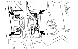
Tighten the 4 nuts in the order shown in the illustration.
9.0 N*m 92 kgf*cm 80 in.*lbf -
Tighten the bolt.
24 N*m 241 kgf*cm 17 ft.*lbf
-
- Click here
INSTALL BRAKE PEDAL SUPPORT SUB-ASSEMBLY (for RHD)
-
Temporarily install the pedal support with the bolt and 4 nuts.
-
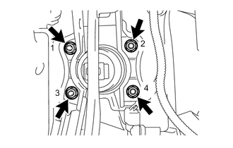
Tighten the 4 nuts in the order shown in the illustration.
9.0 N*m 92 kgf*cm 80 in.*lbf -
Tighten the bolt.
24 N*m 241 kgf*cm 17 ft.*lbf -
Install the wire harness clamp.
-
- Click here
INSTALL NO. 2 STEERING INTERMEDIATE SHAFT ASSEMBLY (for LHD)
-

Align the matchmarks on the No. 2 steering intermediate shaft assembly and the steering column assembly and provisionally install them with the bolt.
Table 1. Text in Illustration *a Matchmark *b Front of the Vehicle -
Tighten the bolt B while aligning the No. 2 steering intermediate shaft assembly with the position C as shown in the illustration.
Standard C 18.5 to 19.7 mm 35 N*m 360 kgf*cm 26 ft.*lbf -
Tighten bolt A.
35 N*m 360 kgf*cm 26 ft.*lbf
-
- Click here
INSTALL BRAKE MASTER CYLINDER PUSH ROD CLEVIS
-
Apply lithium soap base glycol grease to the push rod pin.
-
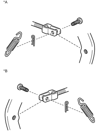
Install the push rod clevis with the push rod pin and a new clip.
Table 2. Text in Illustration *A for LHD *B for RHD 
Apply Lithium Soap Base Glycol Grease -
Install the brake pedal return spring.
-
- Click here
INSTALL STOP LIGHT SWITCH ASSEMBLY
-
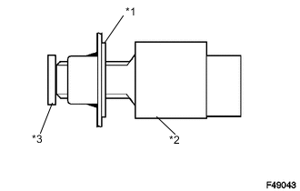
Insert the stop light switch into the adjuster until it just touches the brake pedal.
Table 3. Text in Illustration *1 Adjuster *2 Stop Light Switch Assembly *3 Brake Pedal Note:Do not depress the brake pedal.
-
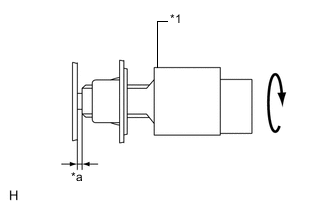
Make a quarter turn clockwise to install the stop light switch.
Table 4. Text in Illustration *1 Stop Light Switch Assembly *a Stop Light Switch Clearance Note:Do not depress the brake pedal.
Tip:The turning torque for installing the stop light switch:
1.5 N*m 15 kgf*cm 13 in.*lbf or less -
Check the stop light switch clearance.
Stop light switch clearance 0.5 to 2.6 mm (0.020 to 0.102 in.) -
Engage the harness clamp to the pedal support.
-
Connect the connector to the stop light switch.
-
- Click here
INSTALL LOWER NO. 1 INSTRUMENT PANEL AIRBAG ASSEMBLY
- Click here
INSTALL COMBINATION METER ASSEMBLY
- Click here
INSPECT AND ADJUST BRAKE PEDAL