STOP LIGHT SWITCH INSTALLATION
CAUTION / NOTICE / HINT
Tech Tips
-
Use the same procedure for RHD and LHD vehicles.
-
The procedure listed below is for LHD vehicles.
PROCEDURE
-
INSTALL STOP LIGHT SWITCH MOUNTING ADJUSTER
-
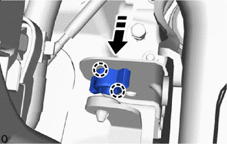

Install in this Direction for LHD:
Attach the claw to install a new stop light switch mounting adjuster.
-
Install in this Direction for RHD:
Attach the claw to install a new stop light switch mounting adjuster.
-
-
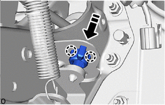
INSTALL STOP LIGHT SWITCH ASSEMBLY
-
for LHD:
-
Insert the stop light switch assembly to the stop light switch mounting adjuster until the switch body slightly touches the brake pedal.
Note
Do not depress the brake pedal.
-
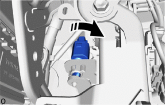
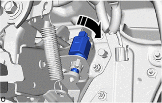
Clockwise Rotate the stop light switch assembly clockwise by approximately one fourth of a rotation.
-
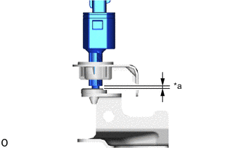
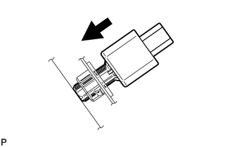
*a Protrusion Amount Measurement Area Check the protrusion amount of the shaft.
Standard 1.5 to 2.6 mm (0.0591 to 0.1024 in.) -
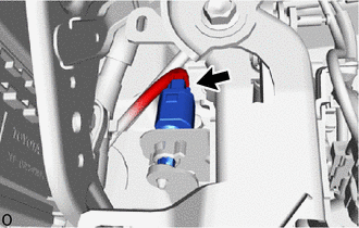
Connect the connector.
-
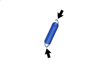

Apply MP Grease Here Apply MP grease to the hook portion of the return spring.
-
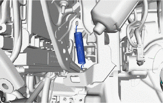
Install the return spring.
-
-
for RHD:
-
Insert the stop light switch assembly to the stop light switch mounting adjuster until the switch body slightly touches the brake pedal.
Note
Do not depress the brake pedal.
-
Clockwise Rotate the stop light switch assembly clockwise by approximately one fourth of a rotation.
-
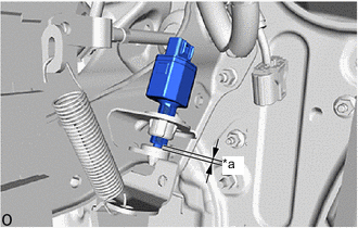
*a Protrusion Amount Measurement Area Check the protrusion amount of the shaft.
Standard 0.5 to 2.6 mm (0.0197 to 0.1024 in.) -
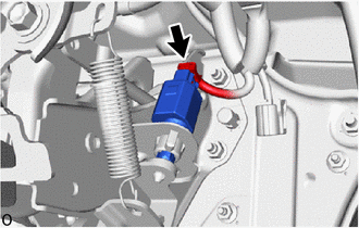
Connect the connector.
-
-
-
INSTALL LOWER NO. 1 INSTRUMENT PANEL AIRBAG ASSEMBLY (for LHD)
-
INSTALL ACCELERATOR PEDAL SENSOR ASSEMBLY (for RHD)
-
CONNECT CABLE TO NEGATIVE AUXILIARY BATTERY TERMINAL
Note
When disconnecting the cable, some systems need to be initialized after the cable is reconnected.
-
INSTALL LUGGAGE COMPARTMENT MAT SUB-ASSEMBLY
-
PERFORM DIAGNOSTIC SYSTEM CHECK
-
CHECK SRS WARNING LIGHT