| DTC Code | DTC Name |
|---|---|
| Stop Light Circuit |
DESCRIPTION
The illumination of the stop lights is controlled by release signals sent to the No. 3 semiconductor power integration ECU from the stop light switch assembly.
CAUTION / NOTICE / HINT
-
First, confirm that there is no malfunction in the power integration system. Refer to the How to Proceed with Troubleshooting procedure.
-
First, confirm that there is no malfunction in the electronically controlled brake system. Refer to the How to Proceed with Troubleshooting procedure.
-
After turning the power switch off, waiting time may be required before disconnecting the cable from the auxiliary battery terminal. Therefore, make sure to read the disconnecting the cable from the auxiliary battery terminal notice before proceeding with work.
PROCEDURE
- Click here
READ VALUE USING GTS
-
Depress the brake pedal.
-
Using the GTS, read the Data List.
- Body Electrical > Power Integration No.3 > Data List
Tester Display Measurement Item Range Normal Condition Diagnostic Note Status of Stop Light Fuse Stop light fuse Connect or Disconnect Connect: Fuse not shut off
Disconnect: Fuse shut off
- -
-
- Body Electrical > Power Integration No.3 > Data List
Tester Display Status of Stop Light Fuse -
-
-
-
OK The Data List value displays "Connect". Result Proceed to OK NG - Body Electrical > Power Integration No.3 > Data List
- OKClick here
- NGClick here
-
- Click here
READ VALUE USING GTS
-
Using the GTS, read the Data List.
- Body Electrical > Power Integration No.3 > Data List
Tester Display Measurement Item Range Normal Condition Diagnostic Note Stop Light Input Signal Stop light switch assembly input signal OFF or ON OFF: Brake pedal released
ON: Brake pedal depressed
- -
-
- Body Electrical > Power Integration No.3 > Data List
Tester Display Stop Light Input Signal -
-
-
-
OK Display changes according to the brake pedal operation. Result Proceed to OK NG - Body Electrical > Power Integration No.3 > Data List
- OKClick here
- NGClick here
-
- Click here
READ VALUE USING GTS
-
Using the GTS, read the Data List.
- Body Electrical > Power Integration No.3 > Data List
Tester Display Measurement Item Range Normal Condition Diagnostic Note Stop Light Output Signal Stop light output condition OFF or ON OFF: Stop light is off
ON: Stop light is on
Stop lights blink during emergency brake signal control -
-
- Body Electrical > Power Integration No.3 > Data List
Tester Display Stop Light Output Signal -
-
-
-
OK Display changes according to the brake pedal operation. Result Proceed to OK NG - Body Electrical > Power Integration No.3 > Data List
- OKClick here
- NG
REPLACE NO. 3 SEMICONDUCTOR POWER INTEGRATION ECUClick here
-
- Click here
CHECK HARNESS AND CONNECTOR (REAR LIGHT LENS AND BODY LH - NO. 3 SEMICONDUCTOR POWER INTEGRATION ECU)
-
Disconnect the cable from the negative (-) auxiliary battery terminal.
-
Disconnect the L111 No. 3 semiconductor power integration ECU connector.
-
Disconnect the L86 rear light lens and body LH connector.
-
Measure the resistance according to the value(s) in the table below.
Standard Resistance Tester Connection Condition Specified Condition L86-6 (B) - L111-1 (OUT) Always Below 1 Ω Result Proceed to OK NG
- OK
REPLACE NO. 3 SEMICONDUCTOR POWER INTEGRATION ECUClick here
- NG
REPAIR OR REPLACE HARNESS OR CONNECTOR
-
- Click here
CHECK HARNESS AND CONNECTOR (STOP LIGHT SWITCH ASSEMBLY - NO. 3 SEMICONDUCTOR POWER INTEGRATION ECU)
-
Disconnect the cable from the negative (-) auxiliary battery terminal.
-
Disconnect the L111 No. 3 semiconductor power integration ECU connector.
-
Disconnect the A3 stop light switch assembly connector.
-
Measure the resistance according to the value(s) in the table below.
Standard Resistance Tester Connection Condition Specified Condition A3-2 (L) - L111-10 (STP) Always Below 1 Ω Result Proceed to OK NG
- OK
REPLACE NO. 3 SEMICONDUCTOR POWER INTEGRATION ECUClick here
- NG
REPAIR OR REPLACE HARNESS OR CONNECTOR
-
- Click here
CHECK REAR LIGHT LENS AND BODY LH
-
Disconnect the L86 rear light lens and body LH connector.
-
Depress the brake pedal.
-
Using the GTS, read the Data List.
- Body Electrical > Power Integration No.3 > Data List
Tester Display Measurement Item Range Normal Condition Diagnostic Note Status of Stop Light Fuse Stop light fuse Connect or Disconnect Connect: Fuse not shut off
Disconnect: Fuse shut off
- -
-
- Body Electrical > Power Integration No.3 > Data List
Tester Display Status of Stop Light Fuse -
-
-
-
OK The Data List value displays "Connect". Result Proceed to OK NG - Body Electrical > Power Integration No.3 > Data List
- OKClick here
- NGClick here
-
- Click here
CHECK REAR LIGHT LED LH
-
Remove the rear light LED LH.
-
Reconnect the L86 rear light lens and body LH connector.
-
Depress the brake pedal.
-
Using the GTS, read the Data List.
- Body Electrical > Power Integration No.3 > Data List
Tester Display Measurement Item Range Normal Condition Diagnostic Note Status of Stop Light Fuse Stop light fuse Connect or Disconnect Connect: Fuse not shut off
Disconnect: Fuse shut off
- -
-
- Body Electrical > Power Integration No.3 > Data List
Tester Display Status of Stop Light Fuse -
-
-
-
OK The Data List value displays "Connect". Result Proceed to OK NG - Body Electrical > Power Integration No.3 > Data List
- OK
REPLACE REAR LIGHT LED LHClick here
- NG
REPLACE REAR LIGHT LENS AND BODY LHClick here
-
- Click here
CHECK REAR LIGHT LENS AND BODY RH
-
Disconnect the L90 rear light lens and body RH connector.
-
Depress the brake pedal.
-
Using the GTS, read the Data List.
- Body Electrical > Power Integration No.3 > Data List
Tester Display Measurement Item Range Normal Condition Diagnostic Note Status of Stop Light Fuse Stop light fuse Connect or Disconnect Connect: Fuse not shut off
Disconnect: Fuse shut off
- -
-
- Body Electrical > Power Integration No.3 > Data List
Tester Display Status of Stop Light Fuse -
-
-
-
OK The Data List value displays "Connect". Result Proceed to OK NG - Body Electrical > Power Integration No.3 > Data List
- OKClick here
- NGClick here
-
- Click here
CHECK REAR LIGHT LED RH
-
Remove the rear light LED RH.
-
Reconnect the L90 rear light lens and body RH connector.
-
Depress the brake pedal.
-
Using the GTS, read the Data List.
- Body Electrical > Power Integration No.3 > Data List
Tester Display Measurement Item Range Normal Condition Diagnostic Note Status of Stop Light Fuse Stop light fuse Connect or Disconnect Connect: Fuse not shut off
Disconnect: Fuse shut off
- -
-
- Body Electrical > Power Integration No.3 > Data List
Tester Display Status of Stop Light Fuse -
-
-
-
OK The Data List value displays "Connect". Result Proceed to OK NG - Body Electrical > Power Integration No.3 > Data List
- OK
REPLACE REAR LIGHT LED RHClick here
- NG
REPLACE REAR LIGHT LENS AND BODY RHClick here
-
- Click here
CHECK REAR COMBINATION LIGHT ASSEMBLY LH
-
Disconnect the L82 rear combination light assembly LH connector.
-
Depress the brake pedal.
-
Using the GTS, read the Data List.
- Body Electrical > Power Integration No.3 > Data List
Tester Display Measurement Item Range Normal Condition Diagnostic Note Status of Stop Light Fuse Stop light fuse Connect or Disconnect Connect: Fuse not shut off
Disconnect: Fuse shut off
- -
-
- Body Electrical > Power Integration No.3 > Data List
Tester Display Status of Stop Light Fuse -
-
-
-
OK The Data List value displays "Connect". Result Proceed to OK NG - Body Electrical > Power Integration No.3 > Data List
- OKClick here
- NGClick here
-
- Click here
CHECK REAR COMBINATION LIGHT LED LH
-
Remove the rear combination light LED LH.
-
Reconnect the L82 rear combination light assembly LH connector.
-
Depress the brake pedal.
-
Using the GTS, read the Data List.
- Body Electrical > Power Integration No.3 > Data List
Tester Display Measurement Item Range Normal Condition Diagnostic Note Status of Stop Light Fuse Stop light fuse Connect or Disconnect Connect: Fuse not shut off
Disconnect: Fuse shut off
- -
-
- Body Electrical > Power Integration No.3 > Data List
Tester Display Status of Stop Light Fuse -
-
-
-
OK The Data List value displays "Connect". Result Proceed to OK NG - Body Electrical > Power Integration No.3 > Data List
- OK
REPLACE REAR COMBINATION LIGHT LED LHClick here
- NG
REPLACE REAR COMBINATION LIGHT LENS AND BODY LHClick here
-
- Click here
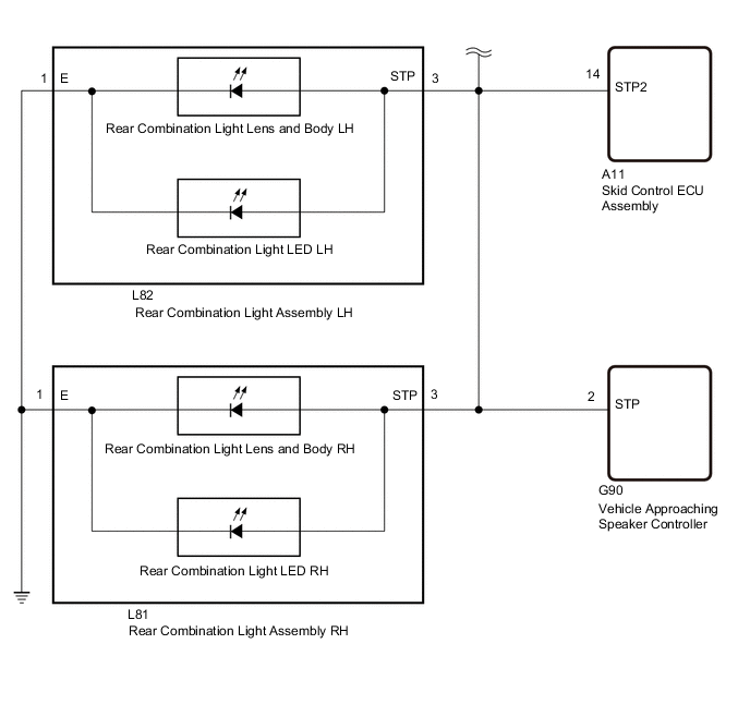
CHECK REAR COMBINATION LIGHT ASSEMBLY RH
-
Disconnect the L81 rear combination light assembly RH connector.
-
Depress the brake pedal.
-
Using the GTS, read the Data List.
- Body Electrical > Power Integration No.3 > Data List
Tester Display Measurement Item Range Normal Condition Diagnostic Note Status of Stop Light Fuse Stop light fuse Connect or Disconnect Connect: Fuse not shut off
Disconnect: Fuse shut off
- -
-
- Body Electrical > Power Integration No.3 > Data List
Tester Display Status of Stop Light Fuse -
-
-
-
OK The Data List value displays "Connect". Result Proceed to OK NG - Body Electrical > Power Integration No.3 > Data List
- OKClick here
- NGClick here
-
- Click here
CHECK REAR COMBINATION LIGHT LED RH
-
Remove the rear combination light LED RH.
-
Reconnect the L81 rear combination light assembly RH connector.
-
Depress the brake pedal.
-
Using the GTS, read the Data List.
- Body Electrical > Power Integration No.3 > Data List
Tester Display Measurement Item Range Normal Condition Diagnostic Note Status of Stop Light Fuse Stop light fuse Connect or Disconnect Connect: Fuse not shut off
Disconnect: Fuse shut off
- -
-
- Body Electrical > Power Integration No.3 > Data List
Tester Display Status of Stop Light Fuse -
-
-
-
OK The Data List value displays "Connect". Result Proceed to OK NG - Body Electrical > Power Integration No.3 > Data List
- OK
REPLACE REAR COMBINATION LIGHT LED RHClick here
- NG
REPLACE REAR COMBINATION LIGHT LENS AND BODY RHClick here
-
- Click here
CHECK CENTER STOP LIGHT WIRE
-
Disconnect the L71 center stop light wire connector.
-
Depress the brake pedal.
-
Using the GTS, read the Data List.
- Body Electrical > Power Integration No.3 > Data List
Tester Display Measurement Item Range Normal Condition Diagnostic Note Status of Stop Light Fuse Stop light fuse Connect or Disconnect Connect: Fuse not shut off
Disconnect: Fuse shut off
- -
-
- Body Electrical > Power Integration No.3 > Data List
Tester Display Status of Stop Light Fuse -
-
-
-
OK The Data List value displays "Connect". Result Proceed to OK NG - Body Electrical > Power Integration No.3 > Data List
- OKClick here
- NGClick here
-
- Click here
CHECK CENTER STOP LIGHT ASSEMBLY
-
Remove the center stop light assembly.
-
Reconnect the L71 center stop light wire connector.
-
Depress the brake pedal.
-
Using the GTS, read the Data List.
- Body Electrical > Power Integration No.3 > Data List
Tester Display Measurement Item Range Normal Condition Diagnostic Note Status of Stop Light Fuse Stop light fuse Connect or Disconnect Connect: Fuse not shut off
Disconnect: Fuse shut off
- -
-
- Body Electrical > Power Integration No.3 > Data List
Tester Display Status of Stop Light Fuse -
-
-
-
OK The Data List value displays "Connect". Result Proceed to OK NG - Body Electrical > Power Integration No.3 > Data List
- OK
REPLACE CENTER STOP LIGHT ASSEMBLYClick here
- NG
REPLACE CENTER STOP LIGHT WIREClick here
-
- Click here
CHECK SKID CONTROL ECU ASSEMBLY
-
Disconnect the A11 skid control ECU assembly connector.
-
Depress the brake pedal.
-
Using the GTS, read the Data List.
- Body Electrical > Power Integration No.3 > Data List
Tester Display Measurement Item Range Normal Condition Diagnostic Note Status of Stop Light Fuse Stop light fuse Connect or Disconnect Connect: Fuse not shut off
Disconnect: Fuse shut off
- -
-
- Body Electrical > Power Integration No.3 > Data List
Tester Display Status of Stop Light Fuse -
-
-
-
OK The Data List value displays "Connect". Result Proceed to OK NG - Body Electrical > Power Integration No.3 > Data List
- OK
REPLACE SKID CONTROL ECU ASSEMBLYClick here
- NGClick here
-
- Click here
CHECK VEHICLE APPROACHING SPEAKER CONTROLLER
-
Disconnect the G90 vehicle approaching speaker controller connector.
-
Depress the brake pedal.
-
Using the GTS, read the Data List.
- Body Electrical > Power Integration No.3 > Data List
Tester Display Measurement Item Range Normal Condition Diagnostic Note Status of Stop Light Fuse Stop light fuse Connect or Disconnect Connect: Fuse not shut off
Disconnect: Fuse shut off
- -
-
- Body Electrical > Power Integration No.3 > Data List
Tester Display Status of Stop Light Fuse -
-
-
-
OK The Data List value displays "Connect". Result Proceed to OK NG - Body Electrical > Power Integration No.3 > Data List
- OK
REPLACE VEHICLE APPROACHING SPEAKER CONTROLLERClick here
- NGClick here
-
- Click here
CHECK HARNESS AND CONNECTOR (REAR LIGHT LENS AND BODY LH - NO. 3 SEMICONDUCTOR POWER INTEGRATION ECU)
-
Disconnect the cable from the negative (-) auxiliary battery terminal.
-
Disconnect the L111 No. 3 semiconductor power integration ECU connector.
-
Disconnect the L86 rear light lens and body LH connector.
-
Disconnect the L90 rear light lens and body RH connector.
-
Disconnect the L82 rear combination light assembly LH connector.
-
Disconnect the L81 rear combination light assembly RH connector.
-
Disconnect the L71 center stop light wire connector.
-
Disconnect the A11 skid control ECU assembly connector.
-
Disconnect the G90 vehicle approaching speaker controller connector.
-
Measure the resistance according to the value(s) in the table below.
Standard Resistance Tester Connection Condition Specified Condition L86-6 (B) or L111-1 (OUT) - Body ground Always 10 kΩ or higher Result Proceed to OK NG
- OK
REPLACE NO. 3 SEMICONDUCTOR POWER INTEGRATION ECUClick here
- NG
REPAIR OR REPLACE HARNESS OR CONNECTOR
-