| DTC Code | DTC Name |
|---|---|
| Taillight Circuit |
DESCRIPTION
The main body ECU (multiplex network body ECU) controls the taillight and license plate light.
CAUTION / NOTICE / HINT
-
Before replacing the main body ECU (multiplex network body ECU), refer to Service Bulletin.
-
First perform the communication function inspections in How to Proceed with Troubleshooting to confirm that there are no CXPI communication malfunctions before troubleshooting this symptom
-
First, confirm that there is no malfunction in the power integration system. Refer to the How to Proceed with Troubleshooting procedure.
-
After turning the power switch off, waiting time may be required before disconnecting the cable from the auxiliary battery terminal. Therefore, make sure to read the disconnecting the cable from the auxiliary battery terminal notice before proceeding with work.
PROCEDURE
- Click here
INSPECT LIGHTS
-
Check the problem symptoms.
Result Result Proceed to All taillights and the license plate light do not illuminate A The rear combination light assembly (taillight) does not illuminate B The rear light assembly (taillight) and license plate light do not illuminate C
-
- Click here
READ VALUE USING GTS
-
Using the GTS, read the Data List.
- Body Electrical > Power Integration No.3 > Data List
Tester Display Measurement Item Range Normal Condition Diagnostic Note Tail Input Signal Light control switch tail position input signal OFF or ON OFF: Light control switch in neither tail nor head position
ON: Light control switch in tail or head position
- -
-
- Body Electrical > Power Integration No.3 > Data List
Tester Display Tail Input Signal -
-
-
-
OK Display changes according to the taillight illumination condition. Result Proceed to OK NG - Body Electrical > Power Integration No.3 > Data List
- OK
REPLACE NO. 3 SEMICONDUCTOR POWER INTEGRATION ECUClick here
- NG
REPLACE MAIN BODY ECU (MULTIPLEX NETWORK BODY ECU)Click here
-
- Click here
READ VALUE USING GTS
-
Turn the taillights on.
-
Using the GTS, read the Data List.
- Body Electrical > Power Integration No.3 > Data List
Tester Display Measurement Item Range Normal Condition Diagnostic Note Status of Tail Light No.1 Fuse Taillight fuse Connect or Disconnect Connect: Fuse not shut off
Disconnect: Fuse shut off
- -
-
- Body Electrical > Power Integration No.3 > Data List
Tester Display Status of Tail Light No.1 Fuse -
-
-
-
OK The Data List value displays "Connect". Result Proceed to OK NG - Body Electrical > Power Integration No.3 > Data List
- OKClick here
- NGClick here
-
- Click here
READ VALUE USING GTS
-
Using the GTS, read the Data List.
- Body Electrical > Power Integration No.3 > Data List
Tester Display Measurement Item Range Normal Condition Diagnostic Note Tail Light No.1 Output Signal Taillight output OFF or ON OFF: Taillight not illuminated
ON: Taillight illuminated
Taillights blink while welcome light is operating -
-
- Body Electrical > Power Integration No.3 > Data List
Tester Display Tail Light No.1 Output Signal -
-
-
-
OK Display changes according to the taillight illumination condition. Result Proceed to OK NG - Body Electrical > Power Integration No.3 > Data List
- OKClick here
- NG
REPLACE NO. 3 SEMICONDUCTOR POWER INTEGRATION ECUClick here
-
- Click here
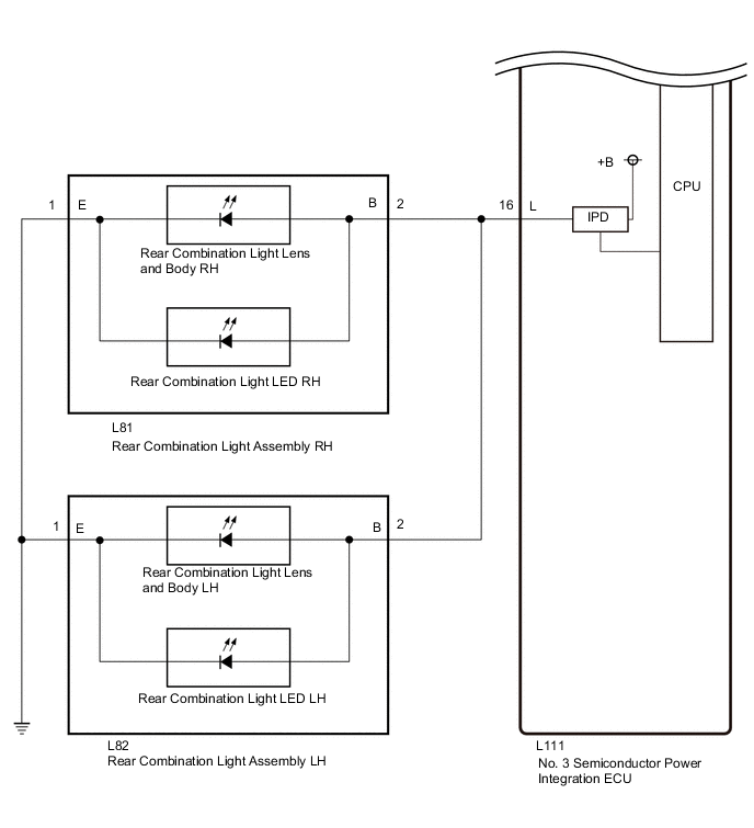
CHECK HARNESS AND CONNECTOR (REAR COMBINATION LIGHT ASSEMBLY LH - NO. 3 SEMICONDUCTOR POWER INTEGRATION ECU)
-
Disconnect the cable from the negative (-) auxiliary battery terminal.
-
Disconnect the L82 rear combination light assembly LH connector.
-
Disconnect the L111 No. 3 semiconductor power integration ECU connector.
-
Measure the resistance according to the value(s) in the table below.
Standard Resistance Tester Connection Condition Specified Condition L82-2 (B) - L111-16 (L) Always Below 1 Ω Result Proceed to OK NG
- OK
REPLACE NO. 3 SEMICONDUCTOR POWER INTEGRATION ECUClick here
- NG
REPAIR OR REPLACE HARNESS OR CONNECTOR
-
- Click here
CHECK REAR COMBINATION LIGHT ASSEMBLY LH
-
Disconnect the L82 rear combination light assembly LH connector.
-
Turn the taillights off.
-
Turn the taillights on.
-
Using the GTS, read the Data List.
- Body Electrical > Power Integration No.3 > Data List
Tester Display Measurement Item Range Normal Condition Diagnostic Note Status of Tail Light No.1 Fuse Taillight fuse Connect or Disconnect Connect: Fuse not shut off
Disconnect: Fuse shut off
- -
-
- Body Electrical > Power Integration No.3 > Data List
Tester Display Status of Tail Light No.1 Fuse -
-
-
-
OK The Data List value displays "Connect". Result Proceed to OK NG - Body Electrical > Power Integration No.3 > Data List
- OKClick here
- NGClick here
-
- Click here
CHECK REAR COMBINATION LIGHT LED LH
-
Remove the rear combination light LED LH.
-
Reconnect the L82 rear combination light assembly LH connector.
-
Turn the taillights off.
-
Turn the taillights on.
-
Using the GTS, read the Data List.
- Body Electrical > Power Integration No.3 > Data List
Tester Display Measurement Item Range Normal Condition Diagnostic Note Status of Tail Light No.1 Fuse Taillight fuse Connect or Disconnect Connect: Fuse not shut off
Disconnect: Fuse shut off
- -
-
- Body Electrical > Power Integration No.3 > Data List
Tester Display Status of Tail Light No.1 Fuse -
-
-
-
OK The Data List value displays "Connect". Result Proceed to OK NG - Body Electrical > Power Integration No.3 > Data List
- OK
REPLACE REAR COMBINATION LIGHT LED LHClick here
- NG
REPLACE REAR COMBINATION LIGHT LENS AND BODY LHClick here
-
- Click here
CHECK REAR COMBINATION LIGHT ASSEMBLY RH
-
Disconnect the L81 rear combination light assembly RH connector.
-
Turn the taillights off.
-
Turn the taillights on.
-
Using the GTS, read the Data List.
- Body Electrical > Power Integration No.3 > Data List
Tester Display Measurement Item Range Normal Condition Diagnostic Note Status of Tail Light No.1 Fuse Taillight fuse Connect or Disconnect Connect: Fuse not shut off
Disconnect: Fuse shut off
- -
-
- Body Electrical > Power Integration No.3 > Data List
Tester Display Status of Tail Light No.1 Fuse -
-
-
-
OK The Data List value displays "Connect". Result Proceed to OK NG - Body Electrical > Power Integration No.3 > Data List
- OKClick here
- NGClick here
-
- Click here
CHECK REAR COMBINATION LIGHT LED RH
-
Remove the rear combination light LED RH.
-
Reconnect the L81 rear combination light assembly RH connector.
-
Turn the taillights off.
-
Turn the taillights on.
-
Using the GTS, read the Data List.
- Body Electrical > Power Integration No.3 > Data List
Tester Display Measurement Item Range Normal Condition Diagnostic Note Status of Tail Light No.1 Fuse Taillight fuse Connect or Disconnect Connect: Fuse not shut off
Disconnect: Fuse shut off
- -
-
- Body Electrical > Power Integration No.3 > Data List
Tester Display Status of Tail Light No.1 Fuse -
-
-
-
OK The Data List value displays "Connect". Result Proceed to OK NG - Body Electrical > Power Integration No.3 > Data List
- OK
REPLACE REAR COMBINATION LIGHT LED RHClick here
- NG
REPLACE REAR COMBINATION LIGHT LENS AND BODY RHClick here
-
- Click here
CHECK HARNESS AND CONNECTOR (REAR COMBINATION LIGHT ASSEMBLY LH - NO. 3 SEMICONDUCTOR POWER INTEGRATION ECU)
-
Disconnect the cable from the negative (-) auxiliary battery terminal.
-
Disconnect the L82 rear combination light assembly LH connector.
-
Disconnect the L81 rear combination light assembly RH connector.
-
Disconnect the L111 No. 3 semiconductor power integration ECU connector.
-
Measure the resistance according to the value(s) in the table below.
Standard Resistance Tester Connection Condition Specified Condition L82-2 (B) or L111-16 (L) - Body ground Always 10 kΩ or higher Result Proceed to OK NG
- OK
REPLACE NO. 3 SEMICONDUCTOR POWER INTEGRATION ECUClick here
- NG
REPAIR OR REPLACE HARNESS OR CONNECTOR
-
- Click here
READ VALUE USING GTS
-
Turn the taillights on.
-
Using the GTS, read the Data List.
- Body Electrical > Power Integration No.3 > Data List
Tester Display Measurement Item Range Normal Condition Diagnostic Note Status of Tail Light No.2 Fuse Taillight fuse Connect or Disconnect Connect: Fuse not shut off
Disconnect: Fuse shut off
- -
-
- Body Electrical > Power Integration No.3 > Data List
Tester Display Status of Tail Light No.2 Fuse -
-
-
-
OK The Data List value displays "Connect". Result Proceed to OK NG - Body Electrical > Power Integration No.3 > Data List
- OKClick here
- NGClick here
-
- Click here
READ VALUE USING GTS
-
Using the GTS, read the Data List.
- Body Electrical > Power Integration No.3 > Data List
Tester Display Measurement Item Range Normal Condition Diagnostic Note Tail Light No.2 Output Signal Taillight output OFF or ON OFF: Taillight not illuminated
ON: Taillight illuminated
Taillights blink while welcome light is operating -
-
- Body Electrical > Power Integration No.3 > Data List
Tester Display Tail Light No.2 Output Signal -
-
-
-
OK Display changes according to the light control switch operation. Result Proceed to OK NG - Body Electrical > Power Integration No.3 > Data List
- OKClick here
- NG
REPLACE NO. 3 SEMICONDUCTOR POWER INTEGRATION ECUClick here
-
- Click here
CHECK HARNESS AND CONNECTOR (REAR LIGHT LENS AND BODY LH - NO. 3 SEMICONDUCTOR POWER INTEGRATION ECU)
-
Disconnect the cable from the negative (-) auxiliary battery terminal.
-
Disconnect the L86 rear light lens and body LH connector.
-
Disconnect the L111 No. 3 semiconductor power integration ECU connector.
-
Measure the resistance according to the value(s) in the table below.
Standard Resistance Tester Connection Condition Specified Condition L86-2 (B) - L111-17 (TAIL) Always Below 1 Ω Result Proceed to OK NG
- OK
REPLACE NO. 3 SEMICONDUCTOR POWER INTEGRATION ECUClick here
- NG
REPAIR OR REPLACE HARNESS OR CONNECTOR
-
- Click here
CHECK REAR LIGHT LENS AND BODY LH
-
Disconnect the L86 rear light lens and body LH connector.
-
Turn the taillights off.
-
Turn the taillights on.
-
Using the GTS, read the Data List.
- Body Electrical > Power Integration No.3 > Data List
Tester Display Measurement Item Range Normal Condition Diagnostic Note Status of Tail Light No.2 Fuse Taillight fuse Connect or Disconnect Connect: Fuse not shut off
Disconnect: Fuse shut off
- -
-
- Body Electrical > Power Integration No.3 > Data List
Tester Display Status of Tail Light No.2 Fuse -
-
-
-
OK The Data List value displays "Connect". Result Proceed to OK NG - Body Electrical > Power Integration No.3 > Data List
- OKClick here
- NGClick here
-
- Click here
CHECK REAR LIGHT LED LH
-
Remove the rear light LED LH.
-
Reconnect the L86 rear light lens and body LH connector.
-
Turn the taillights off.
-
Turn the taillights on.
-
Using the GTS, read the Data List.
- Body Electrical > Power Integration No.3 > Data List
Tester Display Measurement Item Range Normal Condition Diagnostic Note Status of Tail Light No.2 Fuse Taillight fuse Connect or Disconnect Connect: Fuse not shut off
Disconnect: Fuse shut off
- -
-
- Body Electrical > Power Integration No.3 > Data List
Tester Display Status of Tail Light No.2 Fuse -
-
-
-
OK The Data List value displays "Connect". Result Proceed to OK NG - Body Electrical > Power Integration No.3 > Data List
- OK
REPLACE REAR LIGHT LED LHClick here
- NG
REPLACE REAR LIGHT LENS AND BODY LHClick here
-
- Click here
CHECK REAR LIGHT LENS AND BODY RH
-
Disconnect the L90 rear light lens and body RH connector.
-
Turn the taillights off.
-
Turn the taillights on.
-
Using the GTS, read the Data List.
- Body Electrical > Power Integration No.3 > Data List
Tester Display Measurement Item Range Normal Condition Diagnostic Note Status of Tail Light No.2 Fuse Taillight fuse Connect or Disconnect Connect: Fuse not shut off
Disconnect: Fuse shut off
- -
-
- Body Electrical > Power Integration No.3 > Data List
Tester Display Status of Tail Light No.2 Fuse -
-
-
-
OK The Data List value displays "Connect". Result Proceed to OK NG - Body Electrical > Power Integration No.3 > Data List
- OKClick here
- NGClick here
-
- Click here
CHECK REAR LIGHT LED RH
-
Remove the rear light LED RH.
-
Reconnect the L90 rear light lens and body RH connector.
-
Turn the taillights off.
-
Turn the taillights on.
-
Using the GTS, read the Data List.
- Body Electrical > Power Integration No.3 > Data List
Tester Display Measurement Item Range Normal Condition Diagnostic Note Status of Tail Light No.2 Fuse Taillight fuse Connect or Disconnect Connect: Fuse not shut off
Disconnect: Fuse shut off
- -
-
- Body Electrical > Power Integration No.3 > Data List
Tester Display Status of Tail Light No.2 Fuse -
-
-
-
OK The Data List value displays "Connect". Result Proceed to OK NG - Body Electrical > Power Integration No.3 > Data List
- OK
REPLACE REAR LIGHT LED RHClick here
- NG
REPLACE REAR LIGHT LENS AND BODY RHClick here
-
- Click here
CHECK LICENSE PLATE LIGHT ASSEMBLY RH
-
Disconnect the L88 license plate light assembly RH connector.
-
Turn the taillights off.
-
Turn the taillights on.
-
Using the GTS, read the Data List.
- Body Electrical > Power Integration No.3 > Data List
Tester Display Measurement Item Range Normal Condition Diagnostic Note Status of Tail Light No.2 Fuse Taillight fuse Connect or Disconnect Connect: Fuse not shut off
Disconnect: Fuse shut off
- -
-
- Body Electrical > Power Integration No.3 > Data List
Tester Display Status of Tail Light No.2 Fuse -
-
-
-
OK The Data List value displays "Connect". Result Proceed to OK NG - Body Electrical > Power Integration No.3 > Data List
- OK
REPLACE LICENSE PLATE LIGHT ASSEMBLY RHClick here
- NGClick here
-
- Click here
CHECK HARNESS AND CONNECTOR (REAR LIGHT LENS AND BODY LH - NO. 3 SEMICONDUCTOR POWER INTEGRATION ECU)
-
Disconnect the cable from the negative (-) auxiliary battery terminal.
-
Disconnect the L111 No. 3 semiconductor power integration ECU connector.
-
Disconnect the L86 rear light lens and body LH connector.
-
Disconnect the L90 rear light lens and body RH connector.
-
Disconnect the L88 license plate light assembly RH connector.
-
Measure the resistance according to the value(s) in the table below.
Standard Resistance Tester Connection Condition Specified Condition L86-2 (B) or L111-17 (TAIL) - Body ground Always 10 kΩ or higher Result Proceed to OK NG
- OK
REPLACE NO. 3 SEMICONDUCTOR POWER INTEGRATION ECUClick here
- NG
REPAIR OR REPLACE HARNESS OR CONNECTOR
-