| DTC Code | DTC Name |
|---|---|
| B2424 | Lost Communication with Headlight Leveling ECU LH |
| B2425 | Lost Communication with Headlight Leveling ECU RH |
| B2440 | Lost Communication with AHS EDU LH Module |
| B2441 | Lost Communication with AHS EDU RH Module |
DESCRIPTION
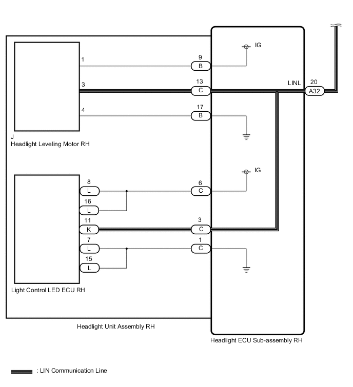
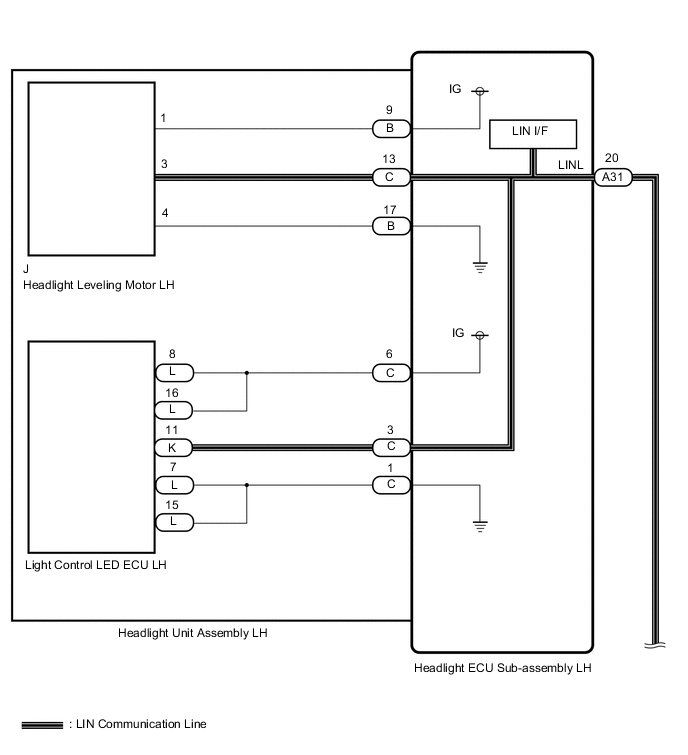
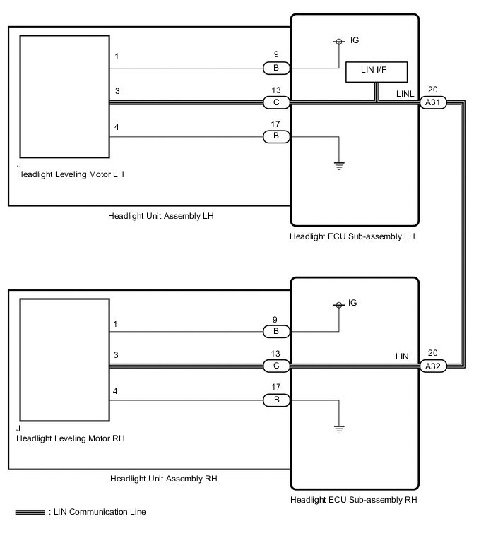
The headlight ECU sub-assembly sends auto leveling control signals to the headlight leveling motor via LIN communication.
The headlight leveling motor operates according to the power supply and control signals from the headlight ECU sub-assembly and sends its operation status to the headlight ECU sub-assembly via LIN communication.
The headlight ECU sub-assembly sends AHS control signals to the light control LED ECU via LIN communication.
The light control LED ECU receives power and control signals from the headlight ECU sub-assembly, controls the additional LEDs and additional fans, and sends its operation status to the headlight ECU sub-assembly via LIN communication.
| DTC No. | Detection Item | DTC Detection Condition | Trouble Area | DTC Output from | Note |
|---|---|---|---|---|---|
| B2424 | Lost Communication with Headlight Leveling ECU LH |
|
|
Headlight ECU sub-assembly LH | - |
| B2425 | Lost Communication with Headlight Leveling ECU RH |
|
|
Headlight ECU sub-assembly LH | - |
| B2440 | Lost Communication with AHS EDU LH Module |
|
|
Headlight ECU sub-assembly LH | w/ Adaptive High Beam System |
| B2441 | Lost Communication with AHS EDU RH Module |
|
|
Headlight ECU sub-assembly LH | w/ Adaptive High Beam System |
| Ouput DTC | Suspected Area (Malfunction Status) | |||
|---|---|---|---|---|
| B2424 | B2425 | B2440 | B2441 | |
| ○ | ○ | ○ | ○ | LIN circuit (short) |
| Headlight ECU sub-assembly LH (Internal malfunction) | ||||
| ○ | - | ○ | - | Headlight ECU sub-assembly LH (Internal malfunction) |
| - | ○ | - | ○ | Headlight ECU sub-assembly RH (Internal malfunction) |
| ○ | - | - | - | Headlight leveling motor LH power supply system abnormal |
| Headlight leveling motor LH (Internal malfunction) | ||||
| Harness open circuit (Headlight ECU sub-assembly LH to headlight leveling motor LH) | ||||
| Headlight ECU sub-assembly LH (Internal malfunction) | ||||
| - | ○ | - | - | Headlight leveling motor RH power supply abnormal |
| Headlight leveling motor RH (Internal malfunction) | ||||
| Harness open circuit (Headlight ECU sub-assembly RH to headlight leveling motor RH) | ||||
| Headlight ECU sub-assembly RH (Internal malfunction) | ||||
| - | - | ○ | - | Light control LED ECU LH power supply system abnormal |
| Light control LED ECU LH (Internal malfunction) | ||||
| Harness open circuit (Headlight ECU sub-assembly LH to light control LED ECU LH) | ||||
| Headlight ECU sub-assembly LH (Internal malfunction) | ||||
| - | - | - | ○ | Light control LED ECU RH power supply system abnormal |
| Light control LED ECU RH (Internal malfunction) | ||||
| Harness open circuit (Headlight ECU sub-assembly RH to light control LED ECU RH) | ||||
| Headlight ECU sub-assembly RH (Internal malfunction) | ||||
| Ouput DTC | Suspected Area (Malfunction Status) | |
|---|---|---|
| B2424 | B2425 | |
| ○ | ○ | LIN circuit (short) |
| Headlight ECU sub-assembly LH (Internal malfunction) | ||
| ○ | - | Headlight leveling motor LH power supply system abnormal |
| Headlight leveling motor LH (Internal malfunction) | ||
| Harness open circuit (Headlight ECU sub-assembly LH to headlight leveling motor LH) | ||
| Headlight ECU sub-assembly LH (Internal malfunction) | ||
| - | ○ | Headlight leveling motor RH power supply abnormal |
| Headlight leveling motor RH (Internal malfunction) | ||
| Harness open circuit (Headlight ECU sub-assembly RH to headlight leveling motor RH) | ||
| Headlight ECU sub-assembly RH (Internal malfunction) | ||
| Headlight ECU sub-assembly LH (Internal malfunction) | ||
CAUTION / NOTICE / HINT
If the headlight ECU sub-assembly LH has been replaced, it is necessary to synchronize the vehicle information and initialize the headlight ECU sub-assembly LH.
PROCEDURE
- Click here
CONFIRM MODEL
-
Choose the model to be inspected.
Result Result Proceed to w/ Adaptive High Beam System A w/o Adaptive High Beam System B
-
- Click here
CHECK FOR DTC
-
Clear the DTCs.
- Body Electrical > AFS > Clear DTCs
-
-
-
Turn the power switch on (IG) and wait for at least 10 seconds or more.
-
Check for DTCs.
- Body Electrical > AFS > Trouble Codes
-
-
Result Result Proceed to DTC B2424, B2425 B2440 and B2441 are not output A DTC B2424, B2425, B2440 and B2441 are output B DTC B2424 and B2440 are output C DTC B2425 and B2441 are output D DTC B2424 is output E DTC B2425 is output F DTC B2440 is output G DTC B2441 is output H
- A
USE SIMULATION METHOD TO CHECKClick here
- BClick here
- C
REPLACE HEADLIGHT ECU SUB-ASSEMBLY LHClick here
- DClick here
- EClick here
- FClick here
- GClick here
- HClick here
-
- Click here
CHECK HEADLIGHT ASSEMBLY RH
-
Disconnect the A32 headlight ECU sub-assembly RH connector.
-
Clear the DTCs.
- Body Electrical > AFS > Clear DTCs
-
-
-
Turn the power switch on (IG) and wait for at least 10 seconds or more.
-
Check for DTCs.
- Body Electrical > AFS > Trouble Codes
-
-
Result Result Proceed to DTC B2424, B2425 B2440 and B2441 are not output A DTC B2425 and B2441 are output B
-
- Click here
CHECK HARNESS AND CONNECTOR (HEADLIGHT ECU SUB-ASSEMBLY LH - HEADLIGHT ECU SUB-ASSEMBLY RH)
-
Disconnect the A31 headlight ECU sub-assembly LH connector.
-
Disconnect the A32 headlight ECU sub-assembly RH connector.
-
Measure the resistance according to the value(s) in the table below.
Standard Resistance Tester Connection Condition Specified Condition A31-20 (LINL) or A32-20 (LINL) - Body ground Always 10 kΩ or higher Result Proceed to OK NG
- OKClick here
- NG
REPAIR OR REPLACE HARNESS OR CONNECTOR
-
- Click here
CHECK HEADLIGHT ECU SUB-ASSEMBLY LH
-
Remove the headlight ECU sub-assembly LH.
-
Reconnect the A31 headlight ECU sub-assembly LH connector.
-
Clear the DTCs.
- Body Electrical > AFS > Clear DTCs
-
-
-
Turn the power switch on (IG) and wait for at least 10 seconds or more.
-
Check for DTCs.
- Body Electrical > AFS > Trouble Codes
-
-
Result Result Proceed to DTC B2424, B2425 B2440 and B2441 are not output A DTC B2424 and B2440 are output B
- A
REPLACE HEADLIGHT ECU SUB-ASSEMBLY LHClick here
- BClick here
-
- Click here
CHECK HEADLIGHT LEVELING MOTOR LH
-
Disconnect the headlight leveling motor LH connector.
-
Reconnect the except headlight leveling motor LH connector.
-
Clear the DTCs.
- Body Electrical > AFS > Clear DTCs
-
-
-
Turn the power switch on (IG) and wait for at least 10 seconds or more.
-
Check for DTCs.
- Body Electrical > AFS > Trouble Codes
-
-
Result Result Proceed to DTC B2424, B2425 B2440 and B2441 are not output A DTC B2424 is output B
- AClick here
- B
REPLACE HEADLIGHT LEVELING MOTOR LHClick here
-
- Click here
CHECK LIGHT CONTROL LED ECU LH
-
Disconnect the light control LED ECU LH connector.
-
Reconnect the except light control LED ECU LH connector.
-
Clear the DTCs.
- Body Electrical > AFS > Clear DTCs
-
-
-
Turn the power switch on (IG) and wait for at least 10 seconds or more.
-
Check for DTCs.
- Body Electrical > AFS > Trouble Codes
-
-
Result Result Proceed to DTC B2424, B2425 B2440 and B2441 are not output A DTC B2440 is output B
- A
REPLACE HEADLIGHT HOUSING SUB-ASSEMBLY LH (WIRE HARNESS)Click here
- B
REPLACE LIGHT CONTROL LED ECU LHClick here
-
- Click here
CHECK HEADLIGHT ECU SUB-ASSEMBLY RH
-
Remove the headlight ECU sub-assembly RH.
-
Reconnect the A32 headlight ECU sub-assembly RH connector.
-
Clear the DTCs.
- Body Electrical > AFS > Clear DTCs
-
-
-
Turn the power switch on (IG) and wait for at least 10 seconds or more.
-
Check for DTCs.
- Body Electrical > AFS > Trouble Codes
-
-
Result Result Proceed to DTC B2424, B2425 B2440 and B2441 are not output A DTC B2425 and B2441 are output B
- A
REPLACE HEADLIGHT ECU SUB-ASSEMBLY RHClick here
- BClick here
-
- Click here
CHECK HEADLIGHT LEVELING MOTOR RH
-
Disconnect the headlight leveling motor RH connector.
-
Reconnect the except headlight leveling motor RH connector.
-
Clear the DTCs.
- Body Electrical > AFS > Clear DTCs
-
-
-
Turn the power switch on (IG) and wait for at least 10 seconds or more.
-
Check for DTCs.
- Body Electrical > AFS > Trouble Codes
-
-
Result Result Proceed to DTC B2424, B2425 B2440 and B2441 are not output A DTC B2425 is output B
- AClick here
- B
REPLACE HEADLIGHT LEVELING MOTOR RHClick here
-
- Click here
CHECK LIGHT CONTROL LED ECU RH
-
Disconnect the light control LED ECU RH connector.
-
Reconnect the except light control LED ECU RH connector.
-
Clear the DTCs.
- Body Electrical > AFS > Clear DTCs
-
-
-
Turn the power switch on (IG) and wait for at least 10 seconds or more.
-
Check for DTCs.
- Body Electrical > AFS > Trouble Codes
-
-
Result Result Proceed to DTC B2424, B2425 B2440 and B2441 are not output A DTC B2441 is output B
- A
REPLACE HEADLIGHT HOUSING SUB-ASSEMBLY RH (WIRE HARNESS)Click here
- B
REPLACE LIGHT CONTROL LED ECU RHClick here
-
- Click here
CHECK HARNESS AND CONNECTOR (HEADLIGHT ECU SUB-ASSEMBLY LH - HEADLIGHT ECU SUB-ASSEMBLY RH)
-
Disconnect the A31 headlight ECU sub-assembly LH connector.
-
Disconnect the A32 headlight ECU sub-assembly RH connector.
-
Measure the resistance according to the value(s) in the table below.
Standard Resistance Tester Connection Condition Specified Condition A31-20 (LINL) - A32-20 (LINL) Always Below 1 Ω Result Proceed to OK NG
- OKClick here
- NG
REPAIR OR REPLACE HARNESS OR CONNECTOR
-
- Click here
CHECK HEADLIGHT ECU SUB-ASSEMBLY RH
-
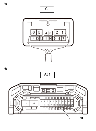
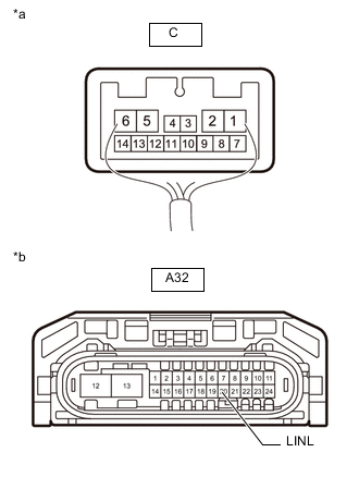
*a Component with harness connected
(Headlight ECU Sub-assembly RH)
*b Front view of wire harness connector
(to Headlight ECU Sub-assembly LH)
Remove the headlight ECU sub-assembly RH as a unit with the connectors still connected.
-
Disconnect the A31 headlight ECU sub-assembly LH connector.
-
Measure the resistance according to the value(s) in the table below.
Standard Resistance Tester Connection Condition Specified Condition C-13 - A31-20 (LINL) Always Below 1 Ω Result Proceed to OK NG
- OK
REPLACE HEADLIGHT ECU SUB-ASSEMBLY LHClick here
- NG
REPLACE HEADLIGHT ECU SUB-ASSEMBLY RHClick here
-
- Click here
CHECK HEADLIGHT UNIT ASSEMBLY LH
-
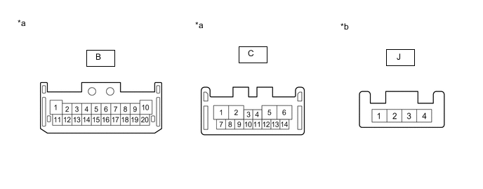
*a Component without harness connected
(Headlight ECU Sub-assembly LH)
*b Component without harness connected
(Headlight Leveling Motor LH)
Remove the headlight unit assembly LH.
-
Measure the resistance according to the value(s) in the table below.
Standard Resistance Tester Connection Wiring Color Condition Specified Condition B-9 - J-1 W-BR Always Below 1 Ω B-17 - J-4 W-G Always Below 1 Ω C-13 - J-3 B-L Always Below 1 Ω Result Proceed to OK NG
- OKClick here
- NG
REPLACE HEADLIGHT HOUSING SUB-ASSEMBLY LH (WIRE HARNESS)Click here
-
- Click here
CHECK HEADLIGHT ECU SUB-ASSEMBLY LH
-
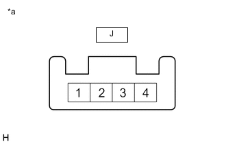
*a Component with harness connected
(Headlight Leveling Motor LH)
Disconnect the headlight leveling motor LH connector.
-
Reconnect the except headlight leveling motor LH connector.
-
Measure the voltage according to the value(s) in the table below.
Standard Voltage Tester Connection Wiring Color Switch Condition Specified Condition J-1 - J-4 W-BR - B-L Power switch on (IG) 11 to 14 V Result Proceed to OK NG
- OKClick here
- NG
REPLACE HEADLIGHT ECU SUB-ASSEMBLY LHClick here
-
- Click here
CHECK HEADLIGHT ECU SUB-ASSEMBLY LH
-
*a Component with harness connected
(Headlight ECU Sub-assembly LH)
*b Front view of wire harness connector
(to Headlight ECU Sub-assembly RH)
Remove the headlight ECU sub-assembly LH as a unit with the connectors still connected.
-
Disconnect the A32 headlight ECU sub-assembly RH connector.
-
Measure the resistance according to the value(s) in the table below.
Standard Resistance Tester Connection Condition Specified Condition C-13 - A32-20 (LINL) Always Below 1 Ω Result Proceed to OK NG
- OK
REPLACE HEADLIGHT LEVELING MOTOR LHClick here
- NG
REPLACE HEADLIGHT ECU SUB-ASSEMBLY LHClick here
-
- Click here
CHECK HEADLIGHT UNIT ASSEMBLY RH
-
*a Component without harness connected
(Headlight ECU Sub-assembly RH)
*b Component without harness connected
(Headlight Leveling Motor RH)
Remove the headlight unit assembly RH.
-
Measure the resistance according to the value(s) in the table below.
Standard Resistance Tester Connection Wiring Color Condition Specified Condition B-9 - J-1 W-BR Always Below 1 Ω B-17 - J-4 W-G Always Below 1 Ω C-13 - J-3 B-L Always Below 1 Ω Result Proceed to OK NG
- OKClick here
- NG
REPLACE HEADLIGHT HOUSING SUB-ASSEMBLY RH (WIRE HARNESS)Click here
-
- Click here
CHECK HEADLIGHT ECU SUB-ASSEMBLY RH
-
*a Component with harness connected
(Headlight Leveling Motor RH)
Disconnect the headlight leveling motor RH connector.
-
Reconnect the except headlight leveling motor RH connector.
-
Measure the voltage according to the value(s) in the table below.
Standard Voltage Tester Connection Wiring Color Switch Condition Specified Condition J-1 - J-4 W-BR - B-L Power switch on (IG) 11 to 14 V Result Proceed to OK NG
- OKClick here
- NG
REPLACE HEADLIGHT ECU SUB-ASSEMBLY RHClick here
-
- Click here
CHECK HEADLIGHT ECU SUB-ASSEMBLY RH
-
*a Component with harness connected
(Headlight ECU Sub-assembly RH)
*b Front view of wire harness connector
(to Headlight ECU Sub-assembly LH)
Remove the headlight ECU sub-assembly RH as a unit with the connectors still connected.
-
Disconnect the A31 headlight ECU sub-assembly LH connector.
-
Measure the resistance according to the value(s) in the table below.
Standard Resistance Tester Connection Condition Specified Condition C-13 - A31-20 (LINL) Always Below 1 Ω Result Proceed to OK NG
- OK
REPLACE HEADLIGHT LEVELING MOTOR RHClick here
- NG
REPLACE HEADLIGHT ECU SUB-ASSEMBLY RHClick here
-
- Click here
CHECK HEADLIGHT UNIT ASSEMBLY LH
-
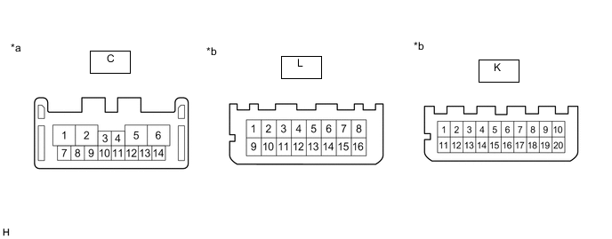
*a Component without harness connected
(Headlight ECU Sub-assembly LH)
*b Component without harness connected
(Light Control LED ECU LH)
Remove the light control LED ECU LH.
-
Measure the resistance according to the value(s) in the table below.
Standard Resistance Tester Connection Wiring Color Condition Specified Condition C-6 - L-8 L Always Below 1 Ω C-6 - L-16 L Always Below 1 Ω C-3 - K-11 R Always Below 1 Ω C-1 - L-7 G Always Below 1 Ω C-1 - L-15 G Always Below 1 Ω Result Proceed to OK NG
- OKClick here
- NG
REPLACE HEADLIGHT HOUSING SUB-ASSEMBLY LH (WIRE HARNESS)Click here
-
- Click here
CHECK HEADLIGHT ECU SUB-ASSEMBLY LH
-
*a Component with harness connected
(Light Control LED ECU LH)
Disconnect the light control LED ECU LH connector.
-
Reconnect the except light control LED ECU LH connector.
-
Measure the voltage according to the value(s) in the table below.
Standard Voltage Tester Connection Wiring Color Switch Condition Specified Condition L-8 - L-7 L - G Power switch on (IG) 11 to 14 V Result Proceed to OK NG
- OKClick here
- NG
REPLACE HEADLIGHT ECU SUB-ASSEMBLY LHClick here
-
- Click here
CHECK HEADLIGHT ECU SUB-ASSEMBLY LH
-
*a Component with harness connected
(Headlight ECU Sub-assembly LH)
*b Front view of wire harness connector
(to Headlight ECU Sub-assembly RH)
Remove the headlight ECU sub-assembly LH as a unit with the connectors still connected.
-
Disconnect the A32 headlight ECU sub-assembly RH connector.
-
Measure the resistance according to the value(s) in the table below.
Standard Resistance Tester Connection Condition Specified Condition C-3 - A32-20 (LINL) Always Below 1 Ω Result Proceed to OK NG
- OK
REPLACE LIGHT CONTROL LED ECU LHClick here
- NG
REPLACE HEADLIGHT ECU SUB-ASSEMBLY LHClick here
-
- Click here
CHECK HEADLIGHT UNIT ASSEMBLY RH
-
*a Component without harness connected
(Headlight ECU Sub-assembly RH)
*b Component without harness connected
(Light Control LED ECU RH)
Remove the light control LED ECU RH.
-
Measure the resistance according to the value(s) in the table below.
Standard Resistance Tester Connection Wiring Color Condition Specified Condition C-6 - L-8 L Always Below 1 Ω C-6 - L-16 L Always Below 1 Ω C-3 - K-11 R Always Below 1 Ω C-1 - L-7 G Always Below 1 Ω C-1 - L-15 G Always Below 1 Ω Result Proceed to OK NG
- OKClick here
- NG
REPLACE HEADLIGHT HOUSING SUB-ASSEMBLY RH (WIRE HARNESS)Click here
-
- Click here
CHECK HEADLIGHT ECU SUB-ASSEMBLY RH
-
*a Component with harness connected
(Light Control LED ECU RH)
Disconnect the light control LED ECU RH connector.
-
Reconnect the except light control LED ECU RH connector.
-
Measure the voltage according to the value(s) in the table below.
Standard Voltage Tester Connection Wiring Color Switch Condition Specified Condition L-8 - L-7 L - G Power switch on (IG) 11 to 14 V Result Proceed to OK NG
- OKClick here
- NG
REPLACE HEADLIGHT ECU SUB-ASSEMBLY RHClick here
-
- Click here
CHECK HEADLIGHT ECU SUB-ASSEMBLY RH
-
*a Component with harness connected
(Headlight ECU Sub-assembly RH)
*b Front view of wire harness connector
(to Headlight ECU Sub-assembly LH)
Remove the headlight ECU sub-assembly RH as a unit with the connectors still connected.
-
Disconnect the A31 headlight ECU sub-assembly LH connector.
-
Measure the resistance according to the value(s) in the table below.
Standard Resistance Tester Connection Condition Specified Condition C-13 - A31-20 (LINL) Always Below 1 Ω Result Proceed to OK NG
- OK
REPLACE LIGHT CONTROL LED ECU RHClick here
- NG
REPLACE HEADLIGHT ECU SUB-ASSEMBLY RHClick here
-
- Click here
CHECK FOR DTC
-
Clear the DTCs.
- Body Electrical > AFS > Clear DTCs
-
-
-
Turn the power switch on (IG) and wait for at least 10 seconds or more.
-
Check for DTCs.
- Body Electrical > AFS > Trouble Codes
-
-
Result Result Proceed to DTC B2424 and B2425 are not output A DTC B2424 and B2425 are output B DTC B2424 is output C DTC B2425 is output D
- A
USE SIMULATION METHOD TO CHECKClick here
- BClick here
- CClick here
GO TO STEP 13
- DClick here
GO TO STEP 16
-
- Click here
CHECK HEADLIGHT ASSEMBLY RH
-
Disconnect the A32 headlight ECU sub-assembly RH connector.
-
Clear the DTCs.
- Body Electrical > AFS > Clear DTCs
-
-
-
Turn the power switch on (IG) and wait for at least 10 seconds or more.
-
Check for DTCs.
- Body Electrical > AFS > Trouble Codes
-
-
Result Result Proceed to DTC B2424 and B2425 are not output A DTC B2425 is output B
-
- Click here
CHECK HARNESS AND CONNECTOR (HEADLIGHT ECU SUB-ASSEMBLY LH - HEADLIGHT ECU SUB-ASSEMBLY RH)
-
Disconnect the A31 headlight ECU sub-assembly LH connector.
-
Disconnect the A32 headlight ECU sub-assembly RH connector.
-
Measure the resistance according to the value(s) in the table below.
Standard Resistance Tester Connection Condition Specified Condition A31-20 (LINL) or A32-20 (LINL) - Body ground Always 10 kΩ or higher Result Proceed to OK NG
- OKClick here
- NG
REPAIR OR REPLACE HARNESS OR CONNECTOR
-
- Click here
CHECK HEADLIGHT ECU SUB-ASSEMBLY LH
-
Remove the headlight ECU sub-assembly LH.
-
Reconnect the A31 headlight ECU sub-assembly LH connector.
-
Clear the DTCs.
- Body Electrical > AFS > Clear DTCs
-
-
-
Turn the power switch on (IG) and wait for at least 10 seconds or more.
-
Check for DTCs.
- Body Electrical > AFS > Trouble Codes
-
-
Result Result Proceed to DTC B2424 and B2425 are not output A DTC B2424 is output B
- A
REPLACE HEADLIGHT ECU SUB-ASSEMBLY LHClick here
- BClick here
-
- Click here
CHECK HEADLIGHT LEVELING MOTOR LH
-
Disconnect the headlight leveling motor LH connector.
-
Reconnect the except headlight leveling motor LH connector.
-
Clear the DTCs.
- Body Electrical > AFS > Clear DTCs
-
-
-
Turn the power switch on (IG) and wait for at least 10 seconds or more.
-
Check for DTCs.
- Body Electrical > AFS > Trouble Codes
-
-
Result Result Proceed to DTC B2424 and B2425 are not output A DTC B2424 is output B
- A
REPLACE HEADLIGHT HOUSING SUB-ASSEMBLY LH (WIRE HARNESS)Click here
- B
REPLACE HEADLIGHT LEVELING MOTOR LHClick here
-
- Click here
CHECK HEADLIGHT LEVELING MOTOR RH
-
Disconnect the headlight leveling motor RH connector.
-
Reconnect the except headlight leveling motor RH connector.
-
Clear the DTCs.
- Body Electrical > AFS > Clear DTCs
-
-
-
Turn the power switch on (IG) and wait for at least 10 seconds or more.
-
Check for DTCs.
- Body Electrical > AFS > Trouble Codes
-
-
Result Result Proceed to DTC B2424 and B2425 are not output A DTC B2425 is output B
- A
REPLACE HEADLIGHT HOUSING SUB-ASSEMBLY RH (WIRE HARNESS)Click here
- B
REPLACE HEADLIGHT LEVELING MOTOR RHClick here
-