| DTC Code | DTC Name |
|---|---|
| B2494 | Left Cornering Light/Front Side Illuminate Light Malfunction |
| B2495 | Right Cornering Light/Front Side Illuminate Light Malfunction |
DESCRIPTION
The headlight ECU sub-assembly supplies internally boosted voltage to the LED so that the current supplied to the LED is always maintained at a constant value.
These DTCs are also output when the headlight ECU sub-assembly detects malfunctions while monitoring the applied voltage.
| DTC No. | Detection Item | DTC Detection Condition | Trouble Area | DTC Output from | Note |
|---|---|---|---|---|---|
| B2494 | Left Cornering Light/Front Side Illuminate Light Malfunction |
|
|
Headlight ECU sub-assembly LH | w/ Cornering Light |
| B2495 | Right Cornering Light/Front Side Illuminate Light Malfunction |
|
|
Headlight ECU sub-assembly RH | w/ Cornering Light |
CAUTION / NOTICE / HINT
If the headlight ECU sub-assembly LH has been replaced, it is necessary to synchronize the vehicle information and initialize the headlight ECU sub-assembly LH.
PROCEDURE
- Click here
CHECK FOR DTC
-
Clear the DTCs.
- Body Electrical > AFS > Clear DTCs
-
-
- Body Electrical > AFS (Sub) > Clear DTCs
-
-
-
10 seconds elapse after turning the power switch on (IG) and illuminating the cornering lights using the light control switch.
-
Check for DTCs.
- Body Electrical > AFS > Trouble Codes
-
-
- Body Electrical > AFS (Sub) > Trouble Codes
-
-
OK DTC B2494 and B2495 are not output. Result Result Proceed to OK A NG (DTC B2494 is output) B NG (DTC B295A is output) C
- A
USE SIMULATION METHOD TO CHECKClick here
- BClick here
- CClick here
-
- Click here
CHECK HEADLIGHT UNIT ASSEMBLY LH
-
Interchange the headlight unit assembly LH with RH and connect the connectors to them.
-
Clear the DTCs.
- Body Electrical > AFS > Clear DTCs
-
-
-
10 seconds elapse after turning the power switch on (IG) and illuminating the cornering lights using the light control switch.
-
Check for DTCs.
- Body Electrical > AFS > Trouble Codes
-
-
OK DTC B2494 is not output. Result Proceed to OK NG
- OKClick here
- NG
REPLACE HEADLIGHT ECU SUB-ASSEMBLY LHClick here
-
- Click here
INSPECT HEADLIGHT UNIT ASSEMBLY LH
-
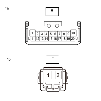
*a Component without harness connected
(Headlight ECU Sub-assembly LH)
*b Component without harness connected
(Headllight Cornering LED Unit LH)
Remove the headllight cornering LED unit LH.
-
Measure the resistance according to the value(s) in the table below.
Standard Resistance Tester Connection Wiring Color Condition Specified Condition B-5 - E-2 B-W Always Below 1 Ω B-6 - E-1 BR Always Below 1 Ω Result Proceed to OK NG
- OK
REPLACE HEADLLIGHT CORNERING LED UNIT LHClick here
- NG
REPLACE HEADLIGHT HOUSING SUB-ASSEMBLY LH (WIRE HARNESS)Click here
-
- Click here
CHECK HEADLIGHT UNIT ASSEMBLY RH
-
Interchange the headlight unit assembly RH with LH and connect the connectors to them.
-
Clear the DTCs.
- Body Electrical > AFS (Sub) > Clear DTCs
-
-
-
10 seconds elapse after turning the power switch on (IG) and illuminating the cornering lights using the light control switch.
-
Check for DTCs.
- Body Electrical > AFS (Sub) > Trouble Codes
-
-
OK DTC B2495 is not output. Result Proceed to OK NG
- OKClick here
- NG
REPLACE HEADLIGHT ECU SUB-ASSEMBLY RHClick here
-
- Click here
INSPECT HEADLIGHT UNIT ASSEMBLY LH
-
*a Component without harness connected
(Headlight ECU Sub-assembly LH)
*b Component without harness connected
(Headllight Cornering LED Unit LH)
Remove the headllight cornering LED unit LH.
-
Measure the resistance according to the value(s) in the table below.
Standard Resistance Tester Connection Wiring Color Condition Specified Condition B-5 - E-2 B-W Always Below 1 Ω B-6 - E-1 BR Always Below 1 Ω Result Proceed to OK NG
- OK
REPLACE HEADLLIGHT CORNERING LED UNIT RHClick here
- NG
REPLACE HEADLIGHT HOUSING SUB-ASSEMBLY RH (WIRE HARNESS)Click here
-