LIGHTING SYSTEM, Diagnostic DTC:B2492, B2493
| DTC Code | DTC Name |
|---|---|
| B2492 | Left Headlight Driver Module Circuit |
| B2493 | Right Headlight Driver Module Circuit |
DESCRIPTION
The headlight ECU sub-assembly sends control signals to the light control LED ECU via LIN communication and controls the additional LEDs using the drive circuit inside the light control LED ECU.
The light control LED ECU applies voltage, which is boosted inside the light control LED ECU to maintain the current applied to the additional LEDs at a constant level, to the additional LEDs and turns on/off each LED based on adaptive high beam system control.
The light control LED ECU also monitors the applied voltage value to detect current application malfunctions.
The light control LED ECU also detects malfunctions in the switching circuit that performs the adaptive high beam system illumination pattern inside the light control LED ECU.
| DTC No. | Detection Item | DTC Detection Condition | Trouble Area | DTC Output from | Note |
|---|---|---|---|---|---|
| B2492 | Left Headlight Driver Module Circuit |
Detection Condition:
Malfunction Status:
Malfunction duration: |
|
Headlight ECU sub-assembly LH | w/ Adaptive High Beam System |
| B2493 | Right Headlight Driver Module Circuit |
Detection Condition:
Malfunction Status:
Malfunction duration: |
|
Headlight ECU sub-assembly LH | w/ Adaptive High Beam System |
WIRING DIAGRAM
-
for LH Side:
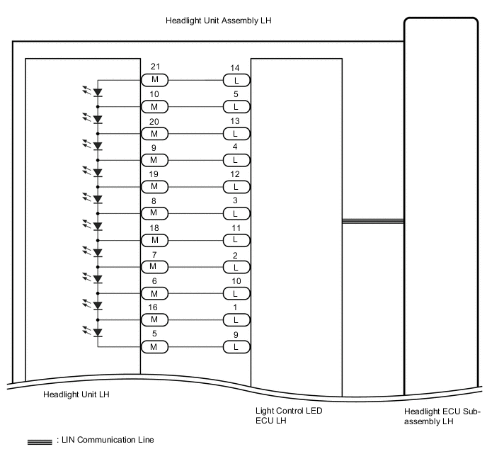
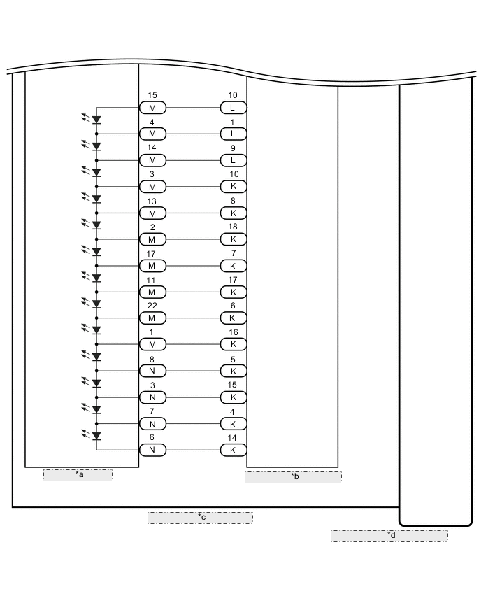
*a Headlight Unit LH *b Light Control LED ECU LH *c Headlight Unit Assembly LH *d Headlight ECU Sub-assembly LH -
for RH Side:
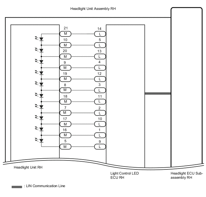
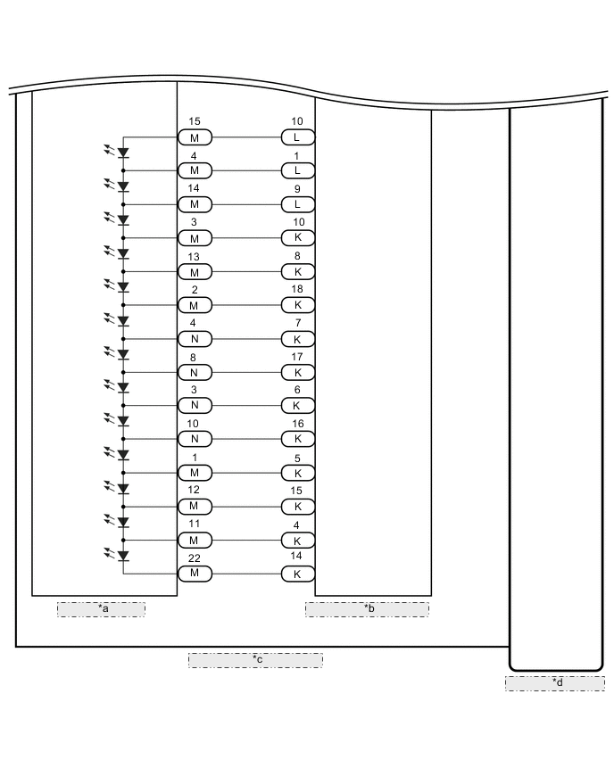
*a Headlight Unit RH *b Light Control LED ECU RH *c Headlight Unit Assembly RH *d Headlight ECU Sub-assembly RH
PROCEDURE
-
CHECK FOR DTC
-
Clear the DTCs.
Body Electrical > AFS > Clear DTCs -
Turning the power switch on (IG) and illuminating the high beam headlights using the light control switch.
-
Check for DTCs.
Body Electrical > AFS > Trouble CodesOK DTC B2492 and B2493 are not output. Result Result Proceed to OK A NG (DTC B2492 is output) B NG (DTC B2493 is output) C
A 
USE SIMULATION METHOD TO CHECK Click here
C 
INSPECT HEADLIGHT UNIT ASSEMBLY RH Click here
B 
-
-
INSPECT HEADLIGHT UNIT ASSEMBLY LH
-
Remove the headlight unit LH.
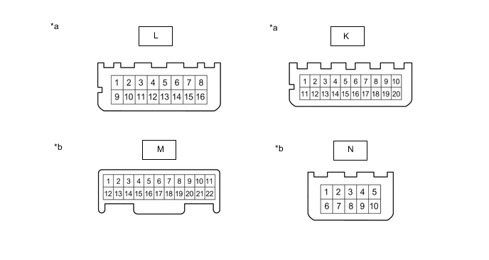
*a Component without harness connected
(Light Control LED ECU LH)
*b Component without harness connected
(Headlight Unit LH)
-
Measure the resistance according to the value(s) in the table below.
Standard Resistance Tester Connection Wiring Color Condition Specified Condition L-14 - M-21 V Always Below 1 Ω L-5 - M-10 W-B Always Below 1 Ω L-13 - M-20 O Always Below 1 Ω L-4 - M-9 GR Always Below 1 Ω L-12 - M-19 Y Always Below 1 Ω L-3 - M-8 R Always Below 1 Ω L-11 - M-18 L Always Below 1 Ω L-2 - M-7 W Always Below 1 Ω L-10 - M-6 G Always Below 1 Ω L-1 - M-16 W-R Always Below 1 Ω L-9 - M-5 B Always Below 1 Ω K-10 - M-15 B-W Always Below 1 Ω K-20 - M-4 W-L Always Below 1 Ω K-9 - M-14 V Always Below 1 Ω K-19 - M-3 W-BR Always Below 1 Ω K-8 - M-13 O Always Below 1 Ω K-18 - M-2 W-G Always Below 1 Ω K-7 - M-17 GR Always Below 1 Ω K-17 - M-11 W-R Always Below 1 Ω K-6 - M-22 L Always Below 1 Ω K-16 - N-1 W-B Always Below 1 Ω K-5 - N-8 BR Always Below 1 Ω K-15 - N-3 B-L Always Below 1 Ω K-4 - N-7 Y Always Below 1 Ω K-14 - N-6 B-R Always Below 1 Ω Result Proceed to OK NG
NG
REPLACE HEADLIGHT HOUSING SUB-ASSEMBLY LH (WIRE HARNESS) Click here
OK
-
-
INSPECT HEADLIGHT UNIT LH
-
Remove the headlight unit LH.
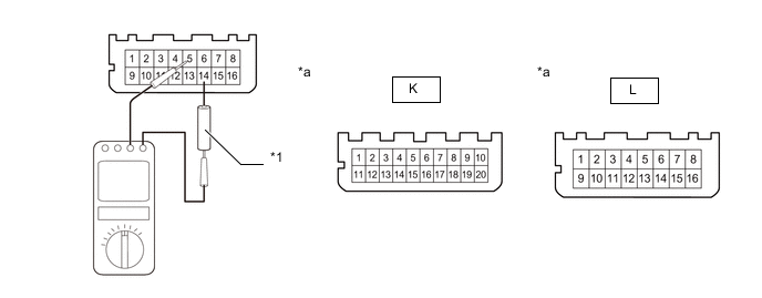
*1 Dry Cell Battery - - *a Component without harness connected
(Light Control LED ECU LH)
- - -
Set the Toyota Electrical Tester to diode check mode.
Tech Tips
If the tester display is below 3 V, replace the dry cell batteries inside the tester.
-
Add 1 dry cell battery (about 1.5 V) between the Toyota Electrical Tester and inspection terminal and check if the LED illuminates.
OK Tester Connection Specified Condition Tester positive (+) - L-14
Tester negative (-) - L-5
LED illuminates Tester positive (+) - L-5
Tester negative (-) - L-13
LED illuminates Tester positive (+) - L-13
Tester negative (-) - L-4
LED illuminates Tester positive (+) - L-4
Tester negative (-) - L-12
LED illuminates Tester positive (+) - L-12
Tester negative (-) - L-3
LED illuminates Tester positive (+) - L-3
Tester negative (-) - L-11
LED illuminates Tester positive (+) - L-11
Tester negative (-) - L-2
LED illuminates Tester positive (+) - L-2
Tester negative (-) - L-10
LED illuminates Tester positive (+) - L-10
Tester negative (-) - L-1
LED illuminates Tester positive (+) - L-1
Tester negative (-) - L-9
LED illuminates Tester positive (+) - K-10
Tester negative (-) - K-20
LED illuminates Tester positive (+) - K-20
Tester negative (-) - K-9
LED illuminates Tester positive (+) - K-9
Tester negative (-) - K-19
LED illuminates Tester positive (+) - K-19
Tester negative (-) - K-8
LED illuminates Tester positive (+) - K-8
Tester negative (-) - K-18
LED illuminates Tester positive (+) - K-18
Tester negative (-) - K-7
LED illuminates Tester positive (+) - K-7
Tester negative (-) - K-11
LED illuminates Tester positive (+) - K-17
Tester negative (-) - K-6
LED illuminates Tester positive (+) - K-6
Tester negative (-) - K-16
LED illuminates Tester positive (+) - K-16
Tester negative (-) - K-5
LED illuminates Tester positive (+) - K-5
Tester negative (-) - K-15
LED illuminates Tester positive (+) - K-15
Tester negative (-) - K-4
LED illuminates Tester positive (+) - K-4
Tester negative (-) - K-14
LED illuminates Result Proceed to OK NG
OK
REPLACE LIGHT CONTROL LED ECU LH Click here
NG
REPLACE HEADLIGHT UNIT LH Click here
-
-
INSPECT HEADLIGHT UNIT ASSEMBLY RH
-
Remove the headlight unit RH.
*a Component without harness connected
(Light Control LED ECU RH)
*b Component without harness connected
(Headlight Unit RH)
-
Measure the resistance according to the value(s) in the table below.
Standard Resistance Tester Connection Wiring Color Condition Specified Condition L-14 - M-21 V Always Below 1 Ω L-5 - M-10 W-B Always Below 1 Ω L-13 - M-20 O Always Below 1 Ω L-4 - M-9 GR Always Below 1 Ω L-12 - M-19 Y Always Below 1 Ω L-3 - M-8 R Always Below 1 Ω L-11 - M-18 L Always Below 1 Ω L-2 - M-7 W Always Below 1 Ω L-10 - M-17 G Always Below 1 Ω L-1 - M-16 W-R Always Below 1 Ω L-9 - M-5 B Always Below 1 Ω K-10 - M-15 B-W Always Below 1 Ω K-20 - M-4 W-L Always Below 1 Ω K-9 - M-14 V Always Below 1 Ω K-19 - M-3 W-BR Always Below 1 Ω K-8 - M-13 O Always Below 1 Ω K-18 - M-2 W-G Always Below 1 Ω K-7 - N-4 GR Always Below 1 Ω K-17 - N-8 W-R Always Below 1 Ω K-6 - N-3 L Always Below 1 Ω K-16 - N-10 W-B Always Below 1 Ω K-5 - M-1 BR Always Below 1 Ω K-15 - M-12 B-L Always Below 1 Ω K-4 - M-11 Y Always Below 1 Ω K-14 - M-22 B-R Always Below 1 Ω Result Proceed to OK NG
NG
REPLACE HEADLIGHT HOUSING SUB-ASSEMBLY RH (WIRE HARNESS) Click here
OK
-
-
INSPECT HEADLIGHT UNIT RH
-
Remove the headlight unit RH.
*1 Dry Cell Battery - - *a Component without harness connected
(Light Control LED ECU RH)
- - -
Set the Toyota Electrical Tester to diode check mode.
Tech Tips
If the tester display is below 3 V, replace the dry cell batteries inside the tester.
-
Add 1 dry cell battery (about 1.5 V) between the Toyota Electrical Tester and inspection terminal and check if the LED illuminates.
OK Tester Connection Specified Condition Tester positive (+) - L-14
Tester negative (-) - L-5
LED illuminates Tester positive (+) - L-5
Tester negative (-) - L-13
LED illuminates Tester positive (+) - L-13
Tester negative (-) - L-4
LED illuminates Tester positive (+) - L-4
Tester negative (-) - L-12
LED illuminates Tester positive (+) - L-12
Tester negative (-) - L-3
LED illuminates Tester positive (+) - L-3
Tester negative (-) - L-11
LED illuminates Tester positive (+) - L-11
Tester negative (-) - L-2
LED illuminates Tester positive (+) - L-2
Tester negative (-) - L-10
LED illuminates Tester positive (+) - L-10
Tester negative (-) - L-1
LED illuminates Tester positive (+) - L-1
Tester negative (-) - L-9
LED illuminates Tester positive (+) - K-10
Tester negative (-) - K-20
LED illuminates Tester positive (+) - K-20
Tester negative (-) - K-9
LED illuminates Tester positive (+) - K-9
Tester negative (-) - K-19
LED illuminates Tester positive (+) - K-19
Tester negative (-) - K-8
LED illuminates Tester positive (+) - K-8
Tester negative (-) - K-18
LED illuminates Tester positive (+) - K-18
Tester negative (-) - K-7
LED illuminates Tester positive (+) - K-7
Tester negative (-) - K-11
LED illuminates Tester positive (+) - K-17
Tester negative (-) - K-6
LED illuminates Tester positive (+) - K-6
Tester negative (-) - K-16
LED illuminates Tester positive (+) - K-16
Tester negative (-) - K-5
LED illuminates Tester positive (+) - K-5
Tester negative (-) - K-15
LED illuminates Tester positive (+) - K-15
Tester negative (-) - K-4
LED illuminates Tester positive (+) - K-4
Tester negative (-) - K-14
LED illuminates Result Proceed to OK NG
OK
REPLACE LIGHT CONTROL LED ECU RH Click here
NG
REPLACE HEADLIGHT UNIT RH Click here
-