| DTC Code | DTC Name |
|---|---|
| B265E | Headrest Front/Rear Sensor Malfunction |
DESCRIPTION
When the position control ECU assembly does not receive a sensor signal despite forward or rearward movement of the seat head rest by power seat motor operation, this DTC is stored.
| DTC No. | Detection Item | DTC Detection Condition | Trouble Area |
|---|---|---|---|
| B2654 | Headrest Sensor Malfunction | The forward and rearward lock detection position of the sensor is the same. |
|
WIRING DIAGRAM
Click here
-
Figure 2. for RHD:
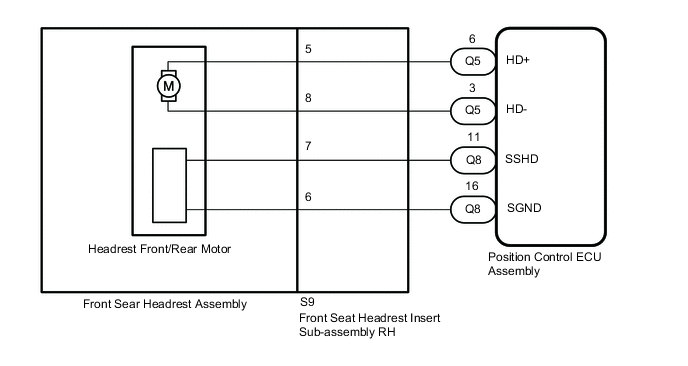 Figure 1. for LHD:
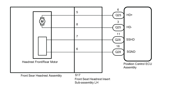
for Driver Seat:
-
Figure 4. for RHD:
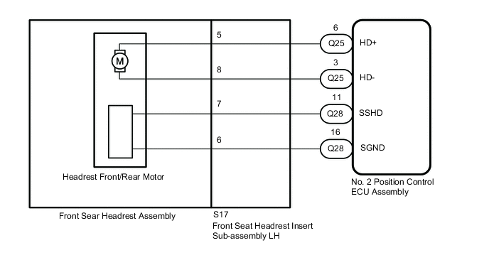 Figure 3. for LHD:
for Front Passenger Seat:
CAUTION / NOTICE / HINT
Initializing the position control ECU assembly will clear the seat position memory.
-
Make sure to initialize the position control ECU assembly after replacing the seat assembly or any related parts (including removal and installation).
-
Before initializing the seat ECU, make sure that the D/C CUT fuse is normal.
-
When any of the following conditions are met, the seat position Information in the position control ECU assembly will be cleared.
-
-
The power switch is turned off with any of the seat switches being operated and the D/C CUT fuse removed.
-
The power switch is turned off within 1 second of any of the seat switches being operated with the D/C CUT fuse removed.
-
PROCEDURE
- Click here
CLEAR DTC
-
Clear the DTCs.
- Body Electrical > Driver Seat > Clear DTCs
-
-
- Body Electrical > Passenger Seat > Clear DTCs
-
-
Result Proceed to NEXT
- NEXTClick here
-
- Click here
CHECK FOR DTC
-
Check for DTCs.
- Body Electrical > Driver Seat > Trouble Codes
-
-
- Body Electrical > Passenger Seat > Trouble Codes
-
-
OK DTC B265E is not output. Result Result Proceed to DTC B265E is not output A DTC B265E output from "Driver Seat" B DTC B265E output from "Front Passenger Seat" C
- A
USE SIMULATION METHOD TO CHECKClick here
- BClick here
- CClick here
-
- Click here
PERFORM ACTIVE TEST USING GTS (HEADREST FRONT/REAR)
-
Connect the GTS to the DLC3.
-
Turn the power switch on (IG).
-
Turn the GTS on.
-
Enter the following menus: Body Electrical / Driver Seat / Active Test.
-
Perform the Active Test according to the display on the GTS.
- Body Electrical > Driver Seat > Active Test
Tester Display Measurement Item Control Range Diagnostic Note Headrest Front/Rear Headrest front/rear operation OFF/Rear/Front - -
-
- Body Electrical > Driver Seat > Active Test
Tester Display Headrest Front/Rear -
-
-
-
OK Motor operates normally. Result Proceed to OK NG - Body Electrical > Driver Seat > Active Test
- OKClick here
- NGClick here
-
- Click here
CHECK POSITION CONTROL ECU ASSEMBLY (HEADRST MOTOR CIRCUIT)
-
for LHD:
-
Disconnect the front seat headrest insert sub-assembly LH (headrest front/rear motor) connector.
-
Measure the voltage according to the value(s) in the table below.
Standard Voltage Tester Connection Switch Condition Specified Condition S17-6 - S17-7 Headrest switch on 4.8 to 5.1 V
-
-
for RHD:
-
Disconnect the front seat headrest insert sub-assembly RH (headrest front/rear motor) connector.
-
Measure the voltage according to the value(s) in the table below.
Standard Voltage Tester Connection Switch Condition Specified Condition S9-6 - S9-7 Headrest switch on 4.8 to 5.1 V
Result Proceed to OK NG -
- OKClick here
- NGClick here
-
- Click here
CHECK FRONT SEAT HEADREST ASSEMBLY
-
Temporarily replace the front seat headrest assembly with front passenger seat's one.
-
Clear the DTCs.
- Body Electrical > Driver Seat > Clear DTCs
-
-
-
Check for DTCs.
- Body Electrical > Driver Seat > Trouble Codes
-
-
OK DTC B265E is not output. Result Proceed to OK NG
- OK
REPLACE FRONT SEAT HEADREST ASSEMBLY
- NG
REPLACE FRONT SEAT HEADREST INSERT SUB-ASSEMBLYClick here
-
- Click here
CHECK HARNESS AND CONNECTOR (POSITION CONTROL ECU ASSEMBLY - FRONT SEAT HEADREST SUB-ASSEMBLY (HEADREST FRONT/REAR MOTOR))
-
for LHD:
-
Disconnect the Q28 position control ECU assembly connector.
-
Disconnect the S17 front seat headrest assembly LH (headrest front/rear motor) connector.
-
Measure the resistance according to the value(s) in the table below.
Standard Resistance Tester Connection Condition Specified Condition Q28-11 (SSHD) - S17-7 Always Below 1 Ω Q28-11 (SSHD) or S17-7 - Other terminals and body ground Always 10 kΩ or higher Q28-16 (SGND) - S17-6 Always Below 1 Ω
-
-
for RHD:
-
Disconnect the Q8 position control ECU assembly connector.
-
Disconnect the S9 front seat headrest insert sub-assembly RH (headrest front/rear motor) connector.
-
Measure the resistance according to the value(s) in the table below.
Standard Resistance Tester Connection Condition Specified Condition Q8-11 (SSHD) - S9-7 Always Below 1 Ω Q8-11 (SSHD) or S9-7 - Other terminals and body ground Always 10 kΩ or higher Q8-16 (SGND) - S9-6 Always Below 1 Ω
Result Proceed to OK NG -
- OK
REPLACE POSITION CONTROL ECU ASSEMBLYClick here
- NG
REPAIR OR REPLACE HARNESS OR CONNECTOR
-
- Click here
INSPECT FRONT SEAT HEADREST ASSEMBLY (HEADREST FRONT/REAR MOTOR)
-
Remove the front seat headrest assembly (headrest front/rear motor).
-
Inspect the front seat headrest assembly (headrest front/rear motor).
Result Proceed to OK NG
- OKClick here
- NG
REPLACE FRONT SEAT HEADREST ASSEMBLY
-
- Click here
CHECK HARNESS AND CONNECTOR (POSITION CONTROL ECU ASSEMBLY - FRONT SEAT HEADREST INSERT SUB-ASSEMBLY (HEADREST FRONT/REAR MOTOR))
-
for LHD:
-
Disconnect the Q25 position control ECU assembly connector.
-
Disconnect the S17 front seat headrest isnert sub-assembly LH (headrest up/down motor) connector.
-
Measure the resistance according to the value(s) in the table below.
Standard Resistance Tester Connection Condition Specified Condition Q25-6 (HD+) - S17-5 Always Below 1 Ω Q25-6 (HD+) or S17-5 - Other terminals and body ground Always 10 kΩ or higher Q25-3 (HD-) - S17-8 Always Below 1 Ω Q25-3 (HD-) or S17-8 - Other terminals and body ground Always 10 kΩ or higher
-
-
for RHD:
-
Disconnect the Q5 position control ECU assembly connector.
-
Disconnect the S9 front seat headrest insert sub-assembly RH (headrest up/down motor) connector.
-
Measure the resistance according to the value(s) in the table below.
Standard Resistance Tester Connection Condition Specified Condition Q5-6 (HD+) - S9-5 Always Below 1 Ω Q5-6 (HD+) or S9-5 - Other terminals and body ground Always 10 kΩ or higher Q5-3 (HD-) - S9-8 Always Below 1 Ω Q5-3 (HD-) or S9-8 - Other terminals and body ground Always 10 kΩ or higher
Result Proceed to OK NG -
- OK
REPLACE POSITION CONTROL ECU ASSEMBLYClick here
- NG
REPAIR OR REPLACE HARNESS OR CONNECTOR
-
- Click here
PERFORM ACTIVE TEST USING GTS (HEADREST FRONT/REAR)
-
Connect the GTS to the DLC3.
-
Turn the power switch on (IG).
-
Turn the GTS on.
-
Enter the following menus: Body Electrical / Passenger Seat / Active Test.
-
Perform the Active Test according to the display on the GTS.
- Body Electrical > Passenger Seat > Active Test
Tester Display Measurement Item Control Range Diagnostic Note Headrest Front/Rear Headrest front/rear operation OFF/Rear/Front - -
-
- Body Electrical > Passenger Seat > Active Test
Tester Display Headrest Front/Rear -
-
-
-
OK Motor operates normally. Result Proceed to OK NG - Body Electrical > Passenger Seat > Active Test
- OKClick here
- NGClick here
-
- Click here
CHECK NO. 2 POSITION CONTROL ECU ASSEMBLY (HEADREST MOTOR CIRCUIT)
-
for LHD:
-
Disconnect the front seat headrest insert sub-assembly RH (headrest front/rear motor) connector.
-
Measure the voltage according to the value(s) in the table below.
Standard Voltage Tester Connection Switch Condition Specified Condition S9-6 - S9-7 Headrest switch on 4.8 to 5.1 V
-
-
for RHD:
-
Disconnect the front seat headrest insert sub-assembly LH (headrest front/rear motor) connector.
-
Measure the voltage according to the value(s) in the table below.
Standard Voltage Tester Connection Switch Condition Specified Condition S17-6 - S17-7 Headrest switch on 4.8 to 5.1 V
Result Proceed to OK NG -
- OKClick here
- NGClick here
-
- Click here
CHECK FRONT SEAT HEADREST ASSEMBLY
-
Temporarily replace the front seat headrest assembly with driver seat's one.
-
Clear the DTCs.
- Body Electrical > Driver Seat > Clear DTCs
-
-
-
Check for DTCs.
- Body Electrical > Driver Seat > Trouble Codes
-
-
OK DTC B265E is not output. Result Proceed to OK NG
- OK
REPLACE FRONT SEAT HEADREST ASSEMBLY
- NG
REPLACE FRONT SEAT HEADREST INSERT SUB-ASSEMBLYClick here
-
- Click here
CHECK HARNESS AND CONNECTOR (NO. 2 POSITION CONTROL ECU ASSEMBLY - FRONT SEAT HEADREST INSERT SUB-ASSEMBLY (HEADREST UP/DOWN MOTOR))
-
for LHD:
-
Disconnect the Q8 No. 2 position control ECU assembly onnector.
-
Disconnect the S9 front seat headrest insert sub-assembly RH (headrest up/down motor) connector.
-
Measure the resistance according to the value(s) in the table below.
Standard Resistance Tester Connection Condition Specified Condition Q8-11 (SSHD) - S9-7 Always Below 1 Ω Q8-11 (SSHD) or S9-7- Other terminals and body ground Always 10 kΩ or higher Q8-16 (SGND) - S9-6 Always Below 1 Ω
-
-
for RHD:
-
Disconnect the Q28 No. 2 position control ECU assembly connector.
-
Disconnect the S17 front seat headrest insert sub-assembly LH (headrest up/down motor) connector.
-
Measure the resistance according to the value(s) in the table below.
Standard Resistance Tester Connection Condition Specified Condition Q28-11 (SSHD) - S17-7 Always Below 1 Ω Q28-11 (SSHD) or S17-7 - Other terminals and body ground Always 10 kΩ or higher Q28-16 (SGND) - S17-6 Always Below 1 Ω
Result Proceed to OK NG -
- OK
REPLACE NO. 2 POSITION CONTROL ECU ASSEMBLYClick here
- NG
REPAIR OR REPLACE HARNESS OR CONNECTOR
-
- Click here
INSPECT FRONT SEAT HEADREST ASSEMBLY (HEADREST FRONT/REAR MOTOR)
-
Remove the front seat headrest assembly (headrest front/rear motor).
-
Inspect the front seat headrest assembly (headrest front/rear motor).
Result Proceed to OK NG
- OKClick here
- NG
REPLACE FRONT SEAT HEADREST INSERT SUB-ASSEMBLYClick here
-
- Click here
CHECK HARNESS AND CONNECTOR (NO. 2 POSITION CONTROL ECU ASSEMBLY - FRONT SEAT HEADREST INSERT SUB-ASSEMBLY (HEADREST FRONT/REAR MOTOR))
-
for LHD:
-
Disconnect the Q5 No. 2 position control ECU assembly connector.
-
Disconnect the S9 front seat headrest insert sub-assembly RH (headrest front/rear motor) connector.
-
Measure the resistance according to the value(s) in the table below.
Standard Resistance Tester Connection Condition Specified Condition Q5-6 (HD+) - S9-5 Always Below 1 Ω Q5-6 (HD+) or S9-5 - Other terminals and body ground Always 10 kΩ or higher Q5-3 (HD-) - S9-8 Always Below 1 Ω Q5-3 (HD-) or S9-8 - Other terminals and body ground Always 10 kΩ or higher
-
-
for RHD:
-
Disconnect the Q25 No. 2 position control ECU assembly connector.
-
Disconnect the S17 front seat headrest insert sub-assembly LH (headrest front/rear motor) connector.
-
Measure the resistance according to the value(s) in the table below.
Standard Resistance Tester Connection Condition Specified Condition Q25-6 (HD+) - S17-5 Always Below 1 Ω Q25-6 (HD+) or S17-5 - Other terminals and body ground Always 10 kΩ or higher Q25-3 (HD-) - S17-8 Always Below 1 Ω Q25-3 (HD-) or S17-8 - Other terminals and body ground Always 10 kΩ or higher
Result Proceed to OK NG -
- OK
REPLACE NO. 2 POSITION CONTROL ECU ASSEMBLYClick here
- NG
REPAIR OR REPLACE HARNESS OR CONNECTOR
-