HEADUP DISPLAY SYSTEM, Diagnostic DTC:B132187
| DTC Code | DTC Name |
|---|---|
| B132187 | Lost Communication with EMV Missing Message |
DESCRIPTION
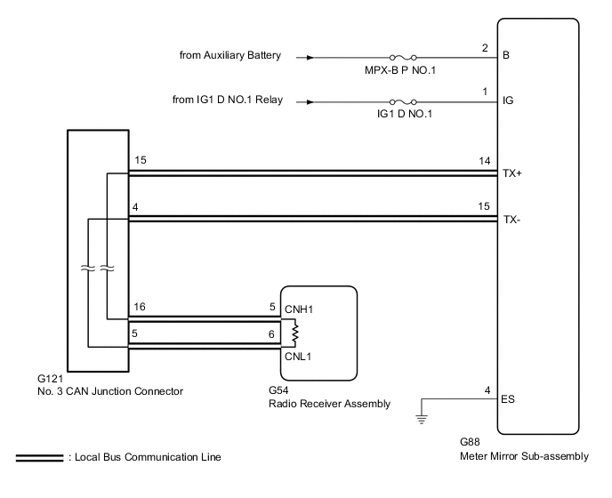
The meter mirror sub-assembly receives signals from the radio receiver assembly via local bus communication and displays audio system and navigation system information on the headup display.
This DTC is stored when the meter mirror sub-assembly cannot receive the signal.
| DTC No. | Detection Item | DTC Detection Condition | Trouble Area | Memory |
|---|---|---|---|---|
| B132187 | Lost Communication with EMV Missing Message |
|
|
DTC stored |
WIRING DIAGRAM
CAUTION / NOTICE / HINT
Note
-
To measure the resistance of the CAN bus, turn the power switch off, wait at least 1 minutes without operating any keys or switches or opening or closing the doors, disconnect the auxiliary battery, wait at least 1 minutes again, and then measure the resistance.
-
After turning the power switch off, waiting time may be required before disconnecting the cable from the negative (-) auxiliary battery terminal. Therefore, make sure to read the disconnecting the cable from the negative (-) auxiliary battery terminal notices before proceeding with work.
-
Inspect the fuses for circuits related to this system before performing the following inspection procedure.
-
When disconnecting the cable from the negative (-) auxiliary battery terminal, refer to Initialization.
-
Communication malfunction DTCs may be output if a radio receiver assembly from another vehicle is installed to this vehicle. Therefore, when replacing the radio receiver assembly, be sure to replace it with a new one.
-
Communication malfunction DTC is output
-
Does not operate normally
Tech Tips
-
When checking each connector, press the connector case in the direction of the connection before disconnecting the connectors, and check that there are no disconnections or looseness.
-
When disconnecting the connectors, check that there is no damage, deformation, or corrosion of the connector terminals and connector case.
-
Depending on the parts that are replaced, performing initialization, registration or calibration may be needed.
PROCEDURE
-
CHECK FOR DTC (NAVIGATION SYSTEM)
-
Check if navigation system DTCs are output.
Body Electrical > Navigation System > Trouble CodesResult Result Proceed to Navigation system DTCs are not output. A Navigation system DTCs are output. B
B 
GO TO NAVIGATION SYSTEM Click here
A 
-
-
CHECK HARNESS AND CONNECTOR (METER MIRROR SUB-ASSEMBLY POWER SOURCE)
-
Disconnect the G88 meter mirror sub-assembly connector.
-
Measure the resistance and voltage according to the value(s) in the table below.
Standard Resistance Tester Connection Condition Specified Condition G88-4 (ES) - Body ground Always Below 1 Ω Standard Voltage Tester Connection Switch Condition Specified Condition G88-2 (B) - Body ground Power switch off 11 to 14 V G88-1 (IG) - Body ground Power switch on (IG) 11 to 14 V Result Proceed to OK NG
NG
REPAIR OR REPLACE HARNESS OR CONNECTOR
OK
-
-
CHECK HARNESS AND CONNECTOR (METER MIRROR SUB-ASSEMBLY - RADIO RECEIVER ASSEMBLY)
-
Disconnect the cable from the negative (-) auxiliary battery terminal.
-
Disconnect the G88 meter mirror sub-assembly connector.
-
Measure the resistance according to the value(s) in the table below.
Standard Resistance Tester Connection Condition Specified Condition G88-14 (TX+) - G88-15 (TX-) Cable disconnected from negative (-) auxiliary battery terminal 54 Ω to 69 Ω Result Proceed to OK NG
NG
REPAIR OR REPLACE HARNESS OR CONNECTOR
OK
-
-
CHECK FOR DTC (METER/GAUGE SYSTEM)
-
Check if meter / gauge system DTCs are output.
Body Electrical > Combination Meter > Trouble CodesResult Result Proceed to DTC B1321 is not output. A DTC B1321 is output. B
A
REPLACE METER MIRROR SUB-ASSEMBLY Click here
B
REPLACE RADIO RECEIVER ASSEMBLY Click here
-