CAUTION / NOTICE / HINT
-
Use the same procedure for RHD and LHD vehicles.
-
The procedure listed below is for LHD vehicles.
PROCEDURE
- Click here
REMOVE FRONT STEERING CONTROL ECU (w/ VGRS)
- Click here
REMOVE LOWER NO. 2 INSTRUMENT PANEL AIRBAG ASSEMBLY (w/o VGRS)
- Click here
REMOVE INSTRUMENT SIDE PANEL LH (w/o VGRS)
- Click here
REMOVE LOWER NO. 1 INSTRUMENT PANEL PAD SUB-ASSEMBLY (w/o VGRS)
- Click here
REMOVE LOWER INSTRUMENT PANEL FINISH PANEL ASSEMBLY WITH AIR CONDITIONING CONTROL ASSEMBLY (w/o VGRS)
- Click here
REMOVE GLOVE COMPARTMENT DOOR PAD PLATE (w/o VGRS)
- Click here
REMOVE GLOVE COMPARTMENT DOOR ASSEMBLY (w/o VGRS)
- Click here
REMOVE PASSENGER SIDE JUNCTION BLOCK ASSEMBLY WITH NETWORK GATEWAY ECU
-
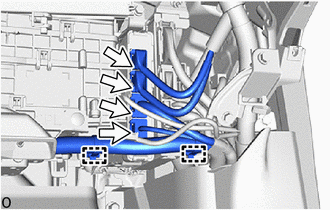
Detach the clamp.
-
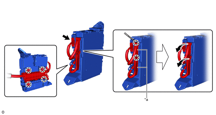
Disconnect the 4 connectors.
-
*a Lever Connector - - 
Rotate in this Direction 
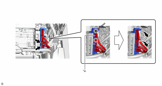
Protective Tape Disconnect the 2 connectors.
-
Using a thin-bladed screwdriver with its tip wrapped with protective tape, detach the claw and disconnect the 2 lever connectors.
-
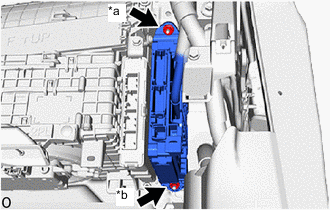
*a Nut (A) *b Nut (B) w/ VGRS:
-
Remove the nut (A).
Note: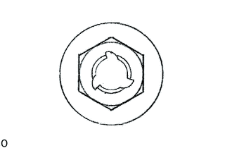
If the removed nut is the same shape as that shown in the illustration, replace it the supplied replacement part.
-
-
w/o VGRS:
-
Remove the nut (A) and nut (B).
Note:
If the removed nut is the same shape as that shown in the illustration, replace it the supplied replacement part.
-
-
*a Lever Connector - - Rotate in this Direction Protective Tape Detach the claw and remove the passenger side junction block with network gateway ECU assembly.
-
Disconnect the connector.
-
Using a thin-bladed screwdriver with its tip wrapped with protective tape, detach the claw and disconnect the 2 lever connectors.
-
- Click here
REMOVE NETWORK GATEWAY ECU
-
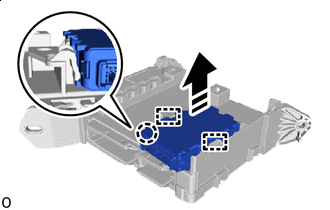
Remove in this Direction Detach the claw and guide and remove the network gateway ECU.
-