| DTC Code | DTC Name |
|---|---|
| Hybrid Battery ECU Communication Stop Mode |
DESCRIPTION
| Detection Item | Symptom | Trouble Area |
|---|---|---|
| Hybrid Battery ECU Communication Stop Mode | Any of the following conditions are met:
|
|
CAUTION / NOTICE / HINT
-
When performing the confirmation driving pattern, obey all speed limits and traffic laws.
-

Before the following operations are conducted, take precautions to prevent electric shock by turning the power switch off, wearing insulated gloves, and removing the service plug grip from HV battery.
-
-
Inspecting the high-voltage system
-
Disconnecting the low voltage connector of the inverter with converter assembly
-
Disconnecting the low voltage connector of the HV battery
-
-
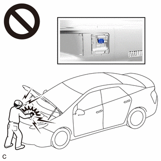
To prevent electric shock, make sure to remove the service plug grip to cut off the high voltage circuit before servicing the vehicle.
-
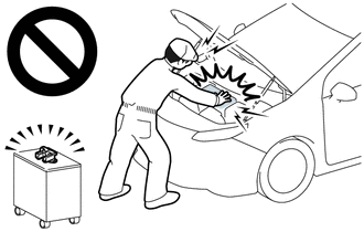
After removing the service plug grip from the HV battery, put it in your pocket to prevent other technicians from accidentally reconnecting it while you are working on the high-voltage system.
-
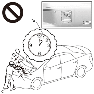
*a Without waiting for 10 minutes After removing the service plug grip, wait for at least 10 minutes before touching any of the high-voltage connectors or terminals. After waiting for 10 minutes, check the voltage at the terminals in the inspection point in the inverter with converter assembly. The voltage should be 0 V before beginning work.
Tip:Waiting for at least 10 minutes is required to discharge the high-voltage capacitor inside the inverter with converter assembly and the electric vehicle charger assembly.
-
Because the order of diagnosis is important to allow correct diagnosis, make sure to begin troubleshooting using How to Proceed with Troubleshooting when CAN communication system related DTCs are output.
-
Inspect the fuses for circuits related to this system before performing the following procedure.
-
Before measuring the resistance of the CAN bus, turn the power switch off and leave the vehicle for 1 minute or more without operating the key or any switches, or opening or closing the doors. After that, disconnect the cable from the negative (-) auxiliary battery terminal and leave the vehicle for 1 minute or more before measuring the resistance.
-
After turning the power switch off, waiting time may be required before disconnecting the cable from the negative (-) auxiliary battery terminal. Therefore, make sure to read the disconnecting the cable from the negative (-) auxiliary battery terminal notices before proceeding with work.
-
Some parts must be initialized and set when replacing or removing and installing parts.
-
After performing repairs, perform the DTC check procedure and confirm that the DTCs are not output again.
DTC check procedure: Turn the power switch on (IG) and wait for 1 minute or more. Then operate the suspected malfunctioning system and drive the vehicle at 60 km/h (37 mph) or more for 5 minutes or more.
-
After the repair, perform the CAN bus check and check that all the ECUs and sensors connected to the CAN communication system are displayed as normal.
-
Before disconnecting related connectors for inspection, push in on each connector body to check that the connector is not loose or disconnected.
-
When a connector is disconnected, check that the terminals and connector body are not cracked, deformed or corroded.
PROCEDURE
- Click here
CHECK FOR OPEN IN CAN BUS WIRE (BATTERY ECU ASSEMBLY BRANCH WIRE)
-
Disconnect the cable from the negative (-) auxiliary battery terminal.
-
Disconnect the Le1 No. 2 HV battery pack wire connector.
-
Measure the resistance according to the value(s) in the table below.
Standard Resistance Tester Connection Condition Specified Condition Le 1-2 (CA2H) - Le 1-11 (CA2L) Cable disconnected from negative (-) auxiliary battery terminal 54 to 69 Ω Result Proceed to OK NG
- OKClick here
- NG
REPAIR OR REPLACE CAN BRANCH WIRE OR CONNECTOR
-
- Click here
CHECK HARNESS AND CONNECTOR (POWER SOURCE CIRCUIT)
-
Measure the resistance according to the value(s) in the table below.
Standard Resistance Tester Connection Condition Specified Condition Le 1-1 (GND) - Body ground Always Below 1 Ω Le 1-10 (GND1) - Body ground Always Below 1 Ω -
Reconnect the cable to the negative (-) auxiliary battery terminal.
Note:When disconnecting the cable, some systems need to be initialized after the cable is reconnected.
-
Measure the voltage according to the value(s) in the table below.
Standard Voltage Tester Connection Switch Condition Specified Condition Le 1-5 (AM) - Body ground Power switch off 11 to 14 V Le 1-14 (IGCT) - Body ground Power switch on (IG) 11 to 14 V Power switch off Below 1 V Result Proceed to OK NG
- OKClick here
- NG
REPAIR OR REPLACE HARNESS OR CONNECTOR (POWER SOURCE CIRCUIT)
-
- Click here
CHECK FOR OPEN IN CAN BUS WIRE (BATTERY ECU ASSEMBLY BRANCH WIRE)
-
Disconnect the cable from the negative (-) auxiliary battery terminal.
-
Disconnect the battery ECU assembly connector.
-
Reconnect the Le1 No. 2 HV battery pack wire connector.
-
Measure the resistance according to the value(s) in the table below.
Standard Resistance Tester Connection Condition Specified Condition e4-13 (CA2H) - e4-12 (CA2L) Cable disconnected from negative (-) auxiliary battery terminal 54 to 69 Ω Result Proceed to OK NG
- OKClick here
- NG
REPAIR OR REPLACE CAN BRANCH WIRE OR CONNECTOR
-
- Click here
CHECK HARNESS AND CONNECTOR (NO. 2 HV BATTERY PACK WIRE)
-
Disconnect the Le1 No. 2 HV battery pack wire connector.
-
Measure the resistance according to the value(s) in the table below.
Standard Resistance Tester Connection Condition Specified Condition Le 1-1 (GND) - e4-11 (GND) Always Below 1 Ω Le 1-5 (AM) - e4-20 (AM) Always Below 1 Ω Le 1-10 (GND1) - e4-31 (GND1) Always Below 1 Ω Le 1-14 (IGCT) - e4-40 (IGCT) Always Below 1 Ω Result Proceed to OK NG
- OK
REPLACE BATTERY ECU ASSEMBLYClick here
- NG
REPAIR OR REPLACE HARNESS OR CONNECTOR (POWER SOURCE CIRCUIT)
-