LIN COMMUNICATION SYSTEM, Diagnostic DTC:B2325
| DTC Code | DTC Name |
|---|---|
| B2325 | LIN Communication Bus Malfunction |
DESCRIPTION
The main body ECU (multiplex network body ECU) intermittently monitors the LIN communication bus between the components related to the doors. DTC B2325 is stored when a malfunction in the LIN communication bus between the components related to the doors is detected consecutively 3 times.
| DTC No. | Detection Item | DTC Detection Condition | Trouble Area |
|---|---|---|---|
| B2325 | LIN Communication Bus Malfunction | Main body ECU (multiplex network body ECU) detects errors in communication with the ECUs connected to the door bus lines 3 times in a row. |
|
-
*1: w/ Sliding Roof System
*2: w/ Hands Free power Trunk Lid
*3: w/ Side Window Curtain
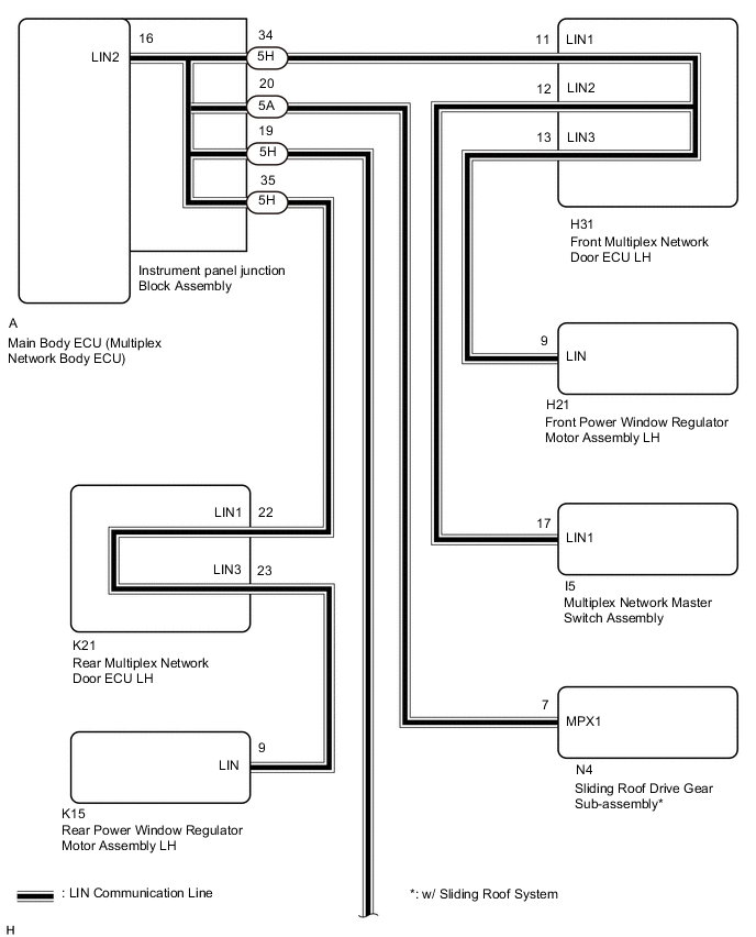
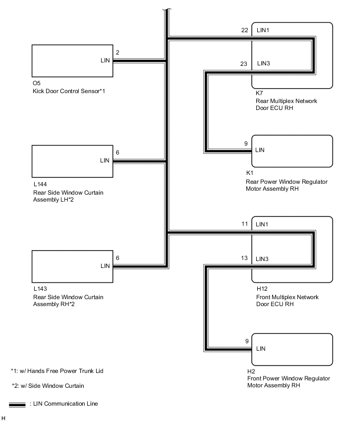
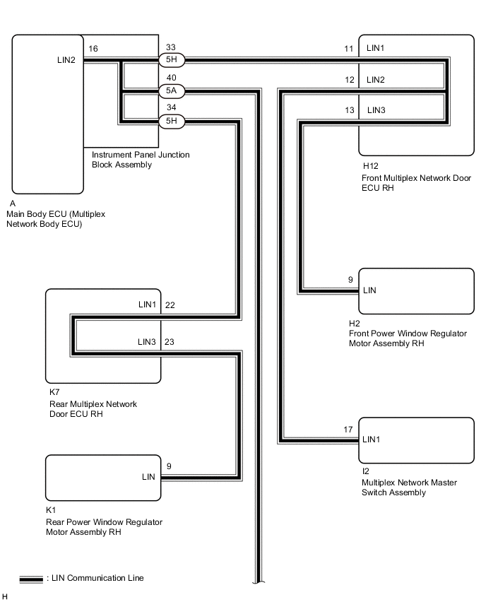
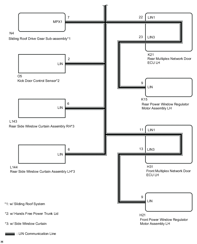
WIRING DIAGRAM
-
for LHD:
-
for RHD:
CAUTION / NOTICE / HINT
Note
-
When using the GTS with the power switch off to troubleshoot:
Connect the GTS to the vehicle and turn a courtesy light switch on and off at 1.5 second intervals until communication between the Techstream and vehicle begins.
-
When the power window regulator motor assembly (driver side) is removed and reinstalled or replaced, the power window regulator motor assembly (driver side) must be initialized.
-
Recognition code registration is necessary when replacing the main body ECU (multiplex network body ECU).
-
If the main body ECU (multiplex network body ECU) is replaced, refer to Service Bulletin.
Tech Tips
When DTC B2325 and a LIN communication stop DTC are output simultaneously, first perform troubleshooting for DTC B2325. Then perform troubleshooting for the LIN communication stop DTC.
PROCEDURE
-
CLEAR DTC
-
Clear the DTCs.
Body Electrical > Main Body > Clear DTCsResult Proceed to NEXT
NEXT 
-
-
CHECK FOR DTC
-
Check for DTCs.
Body Electrical > Main Body > Trouble CodesResult Result Proceed to DTC B2325 is not output A DTC B2325 is output B
A 
USE SIMULATION METHOD TO CHECK Click here
B
-
-
CLEAR DTC
-
Clear the DTCs.
Body Electrical > Main Body > Clear DTCsResult Result Result for LHD A for RHD B
B 
CHECK FRONT MULTIPLEX NETWORK DOOR ECU RH Click here
A
-
-
CHECK FRONT MULTIPLEX NETWORK DOOR ECU LH
-
Disconnect the H31 front multiplex network door ECU LH connector.
-
Check for DTCs.
Body Electrical > Main Body > Trouble CodesResult Result Result DTC B2325 is output A DTC B1206 and B2321 are output B
B
CLEAR DTC Click here
A
-
-
CLEAR DTC
-
Clear the DTCs.
Body Electrical > Main Body > Clear DTCsResult Proceed to NEXT
NEXT
-
-
CHECK FRONT MULTIPLEX NETWORK DOOR ECU RH
-
Disconnect the H12 front multiplex network door ECU RH connector.
-
Check for DTCs.
Body Electrical > Main Body > Trouble CodesResult Result Result DTC B2325 is output A DTC B2322 is output B
B
CLEAR DTC Click here
A
-
-
CLEAR DTC
-
Clear the DTCs.
Body Electrical > Main Body > Clear DTCsResult Proceed to NEXT
NEXT
-
-
CHECK REAR MULTIPLEX NETWORK DOOR ECU LH
-
Disconnect the K21 rear multiplex network door ECU LH connector.
-
Check for DTCs.
Body Electrical > Main Body > Trouble CodesResult Result Result DTC B2325 is output A DTC B2324 is output B
B
CLEAR DTC Click here
A
-
-
CLEAR DTC
-
Clear the DTCs.
Body Electrical > Main Body > Clear DTCsResult Proceed to NEXT
NEXT
-
-
CHECK REAR MULTIPLEX NETWORK DOOR ECU RH
-
Disconnect the K7 rear multiplex network door ECU RH connector.
-
Check for DTCs.
Body Electrical > Main Body > Trouble CodesResult Result Result DTC B2325 is output A DTC B2323 is output B
B
CLEAR DTC Click here
A
-
-
CLEAR DTC
-
Clear the DTCs.
Body Electrical > Main Body > Clear DTCsResult Proceed to NEXT
NEXT
-
-
CHECK SLIDING ROOF DRIVE GEAR SUB-ASSEMBLY
-
Disconnect the N4 sliding roof drive gear sub-assembly connector.
-
Check for DTCs.
Body Electrical > Main Body > Trouble CodesResult Result Result DTC B1273 is output A DTC B2325 is output B
A
REPLACE SLIDING ROOF DRIVE GEAR SUB-ASSEMBLY Click here
B
CLEAR DTC Click here
-
-
CLEAR DTC
-
Clear the DTCs.
Body Electrical > Main Body > Clear DTCsResult Proceed to NEXT
NEXT
-
-
CHECK MULTIPLEX NETWORK MASTER SWITCH ASSEMBLY
-
Disconnect the I5 multiplex network master switch assembly connector.
-
Check for DTCs.
Body Electrical > Main Body > Trouble CodesResult Result Proceed to DTC B1206 is output A DTC B2325 is output B
A
REPLACE MULTIPLEX NETWORK MASTER SWITCH ASSEMBLY Click here
B
CLEAR DTC Click here
-
-
CLEAR DTC
-
Clear the DTCs.
Body Electrical > Main Body > Clear DTCsResult Proceed to NEXT
NEXT
-
-
CHECK FRONT POWER WINDOW REGULATOR MOTOR ASSEMBLY RH
-
Disconnect the H21 front power window regulator motor assembly RH connector.
-
Check for DTCs.
Body Electrical > Main Body > Trouble CodesResult Result Proceed to DTC B2322 is output A DTC B2325 is output B
A
REPLACE FRONT POWER WINDOW REGULATOR MOTOR ASSEMBLY RH Click here
B
CHECK HARNESS AND CONNECTOR (FRONT MULTIPLEX NETWORK DOOR ECU RH - BODY GROUND) Click here
-
-
CLEAR DTC
-
Clear the DTCs.
Body Electrical > Main Body > Clear DTCsResult Proceed to NEXT
NEXT
-
-
CHECK REAR POWER WINDOW REGULATOR MOTOR ASSEMBLY LH
-
Disconnect the K15 rear power window regulator motor assembly LH connector.
-
Check for DTCs.
Body Electrical > Main Body > Trouble CodesResult Result Proceed to DTC B2324 is output A DTC B2325 is output B
A
REPLACE REAR POWER WINDOW REGULATOR MOTOR ASSEMBLY LH Click here
B
CHECK HARNESS AND CONNECTOR (REAR MULTIPLEX NETWORK DOOR ECU LH - BODY GROUND) Click here
-
-
CLEAR DTC
-
Clear the DTCs.
Body Electrical > Main Body > Clear DTCsResult Proceed to NEXT
NEXT
-
-
CHECK REAR POWER WINDOW REGULATOR MOTOR ASSEMBLY RH
-
Disconnect the K1 rear power window regulator motor assembly RH connector.
-
Check for DTCs.
Body Electrical > Main Body > Trouble CodesResult Result Proceed to DTC B2323 is output A DTC B2325 is output B
A
REPLACE REAR POWER WINDOW REGULATOR MOTOR ASSEMBLY RH Click here
B
CHECK HARNESS AND CONNECTOR (REAR MULTIPLEX NETWORK DOOR ECU RH - BODY GROUND) Click here
-
-
CLEAR DTC
-
Clear the DTCs.
Body Electrical > Main Body > Clear DTCsResult Proceed to NEXT
NEXT
-
-
CHECK REAR SIDE WINDOW CURTAIN ASSEMBLY LH
Note
For vehicle without a rear door sunshade, proceed to next step.
-
Disconnect the L144 rear side window curtain assembly LH connector.
-
Check for DTCs.
Body Electrical > Main Body > Trouble CodesResult Result Proceed to DTC B232B is output A DTC B2325 is output B
A
REPLACE REAR SIDE WINDOW CURTAIN ASSEMBLY LH Click here
B
CLEAR DTC Click here
-
-
CLEAR DTC
-
Clear the DTCs.
Body Electrical > Main Body > Clear DTCsResult Proceed to NEXT
NEXT
-
-
CHECK FRONT POWER WINDOW REGULATOR MOTOR ASSEMBLY LH
-
Disconnect the H21 front power window regulator motor assembly LH connector.
-
Check for DTCs.
Body Electrical > Main Body > Trouble CodesResult Result Proceed to DTC B2321 is output A DTC B2325 is output B
A
REPLACE FRONT POWER WINDOW REGULATOR MOTOR ASSEMBLY LH Click here
B
CHECK HARNESS AND CONNECTOR (FRONT MULTIPLEX NETWORK DOOR ECU LH - BODY GROUND) Click here
-
-
CHECK HARNESS AND CONNECTOR (FRONT MULTIPLEX NETWORK DOOR ECU RH - BODY GROUND)
-
Disconnect the H12 front multiplex network door ECU RH connector.
-
Measure the resistance according to the value(s) in the table below.
Standard Resistance Tester Connection Condition Specified Condition H12-13 (LIN3) - Body ground Always 10 kΩ or higher Result Result OK NG
OK
REPLACE FRONT MULTIPLEX NETWORK DOOR ECU RH Click here
NG
REPAIR OR REPLACE HARNESS OR CONNECTOR
-
-
CHECK HARNESS AND CONNECTOR (REAR MULTIPLEX NETWORK DOOR ECU LH - BODY GROUND)
-
Disconnect the K21 rear multiplex network door ECU LH connector.
-
Disconnect the K15 rear rear power window regulator motor assembly LH connector.
-
Measure the resistance according to the value(s) in the table below.
Standard Resistance Tester Connection Condition Specified Condition K21-23 (LIN3) - Body ground Always 10 kΩ or higher Result Result OK NG
OK
REPLACE REAR MULTIPLEX NETWORK DOOR ECU LH Click here
NG
REPAIR OR REPLACE HARNESS OR CONNECTOR
-
-
CHECK HARNESS AND CONNECTOR (REAR MULTIPLEX NETWORK DOOR ECU RH - BODY GROUND)
-
Disconnect the K7 rear multiplex network door ECU RH connector.
-
Disconnect the K1 rear power window regulator motor assembly RH connector.
-
Measure the resistance according to the value(s) in the table below.
Standard Resistance Tester Connection Condition Specified Condition K7-23 (LIN3) - Body ground Always 10 kΩ or higher Result Result OK NG
OK
REPLACE REAR MULTIPLEX NETWORK DOOR ECU RH Click here
NG
REPAIR OR REPLACE HARNESS OR CONNECTOR
-
-
CLEAR DTC
-
Clear the DTCs.
Body Electrical > Main Body > Clear DTCsResult Proceed to NEXT
NEXT
-
-
CHECK REAR SIDE WINDOW CURTAIN ASSEMBLY RH
Note
For vehicle without a rear door sunshade, proceed to next step.
-
Disconnect the L144 rear side window curtain assembly RH connector.
-
Check for DTCs.
Body Electrical > Main Body > Trouble CodesResult Result Proceed to DTC B232A is output A DTC B2325 is output B
A
REPLACE SIDE WINDOW CURTAIN ASSEMBLY REAR RH Click here
B
CLEAR DTC Click here
-
-
CHECK HARNESS AND CONNECTOR (FRONT MULTIPLEX NETWORK DOOR ECU LH - BODY GROUND)
-
Disconnect the H31 front multiplex network door ECU LH connector.
-
Disconnect the H21 front power window regulator motor assembly LH connector.
-
Disconnect the I5 multiplex network master switch assembly connector.
-
Measure the resistance according to the value(s) in the table below.
Standard Resistance Tester Connection Condition Specified Condition H31-12 (LIN2) - Body ground Always 10 kΩ or higher H31-13 (LIN3) - Body ground Always 10 kΩ or higher Result Result OK NG
OK
REPLACE FRONT MULTIPLEX NETWORK DOOR ECU LH Click here
NG
REPAIR OR REPLACE HARNESS OR CONNECTOR
-
-
CLEAR DTC
-
Clear the DTCs.
Body Electrical > Main Body > Clear DTCsResult Proceed to NEXT
NEXT
-
-
CHECK KICK DOOR CONTROL SENSOR
Note
For vehicle without a hands free power back door, proceed to next step.
-
Disconnect the O5 kick door control sensor connector.
-
Check for DTCs.
Body Electrical > Main Body > Trouble CodesResult Result Proceed to DTC B2325 is output A DTC B2325 is not output B
A
REPLACE KICK DOOR CONTROL SENSOR Click here
B
-
-
CHECK HARNESS AND CONNECTOR (MAIN BODY ECU [MULTIPLEX NETWORK BODY ECU] - BODY GROUND)
-
Disconnect the 5H instrument panel junction block assembly connector.
-
Disconnect the H12 front multiplex network door ECU RH connector.
-
Disconnect the H31 front multiplex network door ECU LH connector.
-
Disconnect the K7 rear multiplex network door ECU RH connector.
-
Disconnect the K21 rear multiplex network door ECU LH connector.
-
w/ Sliding Roof System:
-
Disconnect the N4 sliding roof drive gear sub-assembly connector.
-
-
w/ Side Window Curtain:
-
Disconnect the L144 rear side window regulator motor assembly LH connector.
-
Disconnect the L143 rear side window regulator motor assembly RH connector.
-
-
w/ Hands Free Power Trunk Lid:
-
Disconnect the O5 kick door control sensor connector.
-
-
Measure the resistance according to the value(s) in the table below.
Standard Resistance Tester Connection Condition Specified Condition A-16 (LIN2) - Body ground Always 10 kΩ or higher Result Result OK NG
OK
REPLACE MAIN BODY ECU (MULTIPLEX NETWORK BODY ECU) Click here
NG
CHECK HARNESS AND CONNECTOR (INSTRUMENT PANEL JUNCTION BLOCK ASSEMBLY - BODY GROUND) Click here
-
-
CHECK FRONT MULTIPLEX NETWORK DOOR ECU RH
-
Disconnect the H12 front multiplex network door ECU RH connector.
-
Check for DTCs.
Body Electrical > Main Body > Trouble CodesResult Result Result DTC B2325 is output A DTC B1206 and B2321 are output B
B
CLEAR DTC Click here
A
-
-
CLEAR DTC
-
Clear the DTCs.
Body Electrical > Main Body > Clear DTCsResult Proceed to NEXT
NEXT
-
-
CHECK FRONT MULTIPLEX NETWORK DOOR ECU LH
-
Disconnect the H31 front multiplex network door ECU RH connector.
-
Check for DTCs.
Body Electrical > Main Body > Trouble CodesResult Result Result DTC B2325 is output A DTC B2322 is output B
B
CLEAR DTC Click here
A
-
-
CLEAR DTC
-
Clear the DTCs.
Body Electrical > Main Body > Clear DTCsResult Proceed to NEXT
NEXT
-
-
CHECK REAR MULTIPLEX NETWORK DOOR ECU RH
-
Disconnect the K7 rear multiplex network door ECU RH connector.
-
Check for DTCs.
Body Electrical > Main Body > Trouble CodesResult Result Result DTC B2325 is output A DTC B2323 is output B
B
CLEAR DTC Click here
A
-
-
CLEAR DTC
-
Clear the DTCs.
Body Electrical > Main Body > Clear DTCsResult Proceed to NEXT
NEXT
-
-
CHECK REAR MULTIPLEX NETWORK DOOR ECU LH
-
Disconnect the K21 rear multiplex network door ECU LH connector.
-
Check for DTCs.
Body Electrical > Main Body > Trouble CodesResult Result Result DTC B2325 is output A DTC B2324 is output B
B
CLEAR DTC Click here
A
-
-
CLEAR DTC
-
Clear the DTCs.
Body Electrical > Main Body > Clear DTCsResult Proceed to NEXT
NEXT
-
-
CHECK SLIDING ROOF DRIVE GEAR SUB-ASSEMBLY
Note
For vehicle without a sliding roof system, proceed to next step.
-
Disconnect the N4 sliding roof drive gear sub-assembly connector.
-
Check for DTCs.
Body Electrical > Main Body > Trouble CodesResult Result Result DTC B1273 is output A DTC B2325 is output B
A
REPLACE SLIDING ROOF DRIVE GEAR SUB-ASSEMBLY Click here
B
CLEAR DTC Click here
-
-
CHECK HARNESS AND CONNECTOR (INSTRUMENT PANEL JUNCTION BLOCK ASSEMBLY - BODY GROUND)
-
Disconnect the 5A and 5H instrument panel junction block assembly connectors.
-
Disconnect the H12 front multiplex network door ECU RH connector.
-
Disconnect the H31 front multiplex network door ECU LH connector.
-
Disconnect the K7 rear multiplex network door ECU RH connector.
-
Disconnect the K21 rear multiplex network door ECU LH connector.
-
w/ Sliding Roof System:
-
Disconnect the N4 sliding roof drive gear sub-assembly connector.
-
-
w/ Side Window Curtain:
-
Disconnect the L144 rear side window regulator motor assembly LH connector.
-
Disconnect the L143 rear side window regulator motor assembly RH connector.
-
-
w/ Hands Free Power Trunk Lid:
-
Disconnect the O5 kick door control sensor connector.
-
-
Measure the resistance according to the value(s) in the table below.
Standard Resistance Tester Connection Condition Specified Condition 5A-20 - Body ground Always 10 kΩ or higher 5A-34 - Body ground Always 10 kΩ or higher 5A-35 - Body ground Always 10 kΩ or higher 5H-19 - Body ground Always 10 kΩ or higher Result Result OK NG
OK
REPLACE INSTRUMENT PANEL JUNCTION BLOCK ASSEMBLY Click here
NG
REPAIR OR REPLACE HARNESS OR CONNECTOR
-
-
CLEAR DTC
-
Clear the DTCs.
Body Electrical > Main Body > Clear DTCsResult Proceed to NEXT
NEXT
-
-
CHECK MULTIPLEX NETWORK MASTER SWITCH ASSEMBLY
-
Disconnect the I2 multiplex network master switch assembly connector.
-
Check for DTCs.
Body Electrical > Main Body > Trouble CodesResult Result Proceed to DTC B1206 is output A DTC B2325 is output B
A
REPLACE MULTIPLEX NETWORK MASTER SWITCH ASSEMBLY Click here
B
CLEAR DTC Click here
-
-
CLEAR DTC
-
Clear the DTCs.
Body Electrical > Main Body > Clear DTCsResult Proceed to NEXT
NEXT
-
-
CHECK HARNESS AND CONNECTOR (FRONT MULTIPLEX NETWORK DOOR ECU RH - BODY GROUND)
-
Disconnect the H12 front multiplex network door ECU RH connector.
-
Disconnect the I2 multiplex network master switch assembly connector.
-
Measure the resistance according to the value(s) in the table below.
Standard Resistance Tester Connection Condition Specified Condition H12-13 (LIN3) - Body ground Always 10 kΩ or higher Result Result OK NG
OK
REPLACE FRONT MULTIPLEX NETWORK DOOR ECU RH Click here
NG
REPAIR OR REPLACE HARNESS OR CONNECTOR
-
-
CLEAR DTC
-
Clear the DTCs.
Body Electrical > Main Body > Clear DTCsResult Proceed to NEXT
NEXT
-
-
CHECK REAR POWER WINDOW REGULATOR MOTOR ASSEMBLY LH
-
Disconnect the K15 rear power window regulator motor assembly LH connector.
-
Check for DTCs.
Body Electrical > Main Body > Trouble CodesResult Result Proceed to DTC B2324 is output A DTC B2325 is output B
A
REPLACE REAR POWER WINDOW REGULATOR MOTOR ASSEMBLY LH Click here
B
CHECK HARNESS AND CONNECTOR (REAR MULTIPLEX NETWORK DOOR ECU LH - BODY GROUND) Click here
-
-
CLEAR DTC
-
Clear the DTCs.
Body Electrical > Main Body > Clear DTCsResult Proceed to NEXT
NEXT
-
-
CHECK REAR POWER WINDOW REGULATOR MOTOR ASSEMBLY RH
-
Disconnect the K1 rear power window regulator motor assembly RH connector.
-
Check for DTCs.
Body Electrical > Main Body > Trouble CodesResult Result Proceed to DTC B2323 is output A DTC B2325 is output B
A
REPLACE REAR POWER WINDOW REGULATOR MOTOR ASSEMBLY RH Click here
B
CHECK HARNESS AND CONNECTOR (REAR MULTIPLEX NETWORK DOOR ECU RH - BODY GROUND) Click here
-
-
CLEAR DTC
-
Clear the DTCs.
Body Electrical > Main Body > Clear DTCsResult Proceed to NEXT
NEXT
-
-
CHECK REAR SIDE WINDOW CURTAIN ASSEMBLY RH
Note
For vehicle without a rear door sunshade, proceed to next step.
-
Disconnect the L143 rear side window curtain assembly RH connector.
-
Check for DTCs.
Body Electrical > Main Body > Trouble CodesResult Result Proceed to DTC B232A is output A DTC B2325 is output B
A
REPLACE REAR SIDE WINDOW CURTAIN ASSEMBLY RH Click here
B
CLEAR DTC Click here
-
-
CLEAR DTC
-
Clear the DTCs.
Body Electrical > Main Body > Clear DTCsResult Proceed to NEXT
NEXT
-
-
CHECK FRONT POWER WINDOW REGULATOR MOTOR ASSEMBLY RH
-
Disconnect the H2 front power window regulator motor assembly RH connector.
-
Check for DTCs.
Body Electrical > Main Body > Trouble CodesResult Result Proceed to DTC B2321 is output A DTC B2325 is output B
A
REPLACE FRONT POWER WINDOW REGULATOR MOTOR ASSEMBLY RH Click here
B
CHECK HARNESS AND CONNECTOR (FRONT MULTIPLEX NETWORK DOOR ECU RH - BODY GROUND) Click here
-
-
CHECK HARNESS AND CONNECTOR (REAR MULTIPLEX NETWORK DOOR ECU LH - BODY GROUND)
-
Disconnect the K21 rear multiplex network door ECU LH connector.
-
Disconnect the K15 rear power window regulator motor assembly LH connector.
-
Measure the resistance according to the value(s) in the table below.
Standard Resistance Tester Connection Condition Specified Condition K21-23 (LIN3) - Body ground Always 10 kΩ or higher Result Result OK NG
OK
REPLACE REAR MULTIPLEX NETWORK DOOR ECU LH Click here
NG
REPAIR OR REPLACE HARNESS OR CONNECTOR
-
-
CHECK HARNESS AND CONNECTOR (REAR MULTIPLEX NETWORK DOOR ECU RH - BODY GROUND)
-
Disconnect the K7 rear multiplex network door ECU RH connector.
-
Disconnect the K1 rear power window regulator motor assembly RH connector.
-
Measure the resistance according to the value(s) in the table below.
Standard Resistance Tester Connection Condition Specified Condition K7-23 (LIN3) - Body ground Always 10 kΩ or higher Result Result OK NG
OK
REPLACE REAR MULTIPLEX NETWORK DOOR ECU RH Click here
NG
REPAIR OR REPLACE HARNESS OR CONNECTOR
-
-
CLEAR DTC
-
Clear the DTCs.
Body Electrical > Main Body > Clear DTCsResult Proceed to NEXT
NEXT
-
-
CHECK REAR SIDE WINDOW CURTAIN ASSEMBLY LH
Note
For vehicle without a rear door sunshade, proceed to next step.
-
Disconnect the L144 rear side window curtain assembly LH connector.
-
Check for DTCs.
Body Electrical > Main Body > Trouble CodesResult Result Proceed to DTC B232B is output A DTC B2325 is output B
A
REPLACE REAR SIDE WINDOW CURTAIN ASSEMBLY LH Click here
B
CLEAR DTC Click here
-
-
CHECK HARNESS AND CONNECTOR (FRONT MULTIPLEX NETWORK DOOR ECU RH - BODY GROUND)
-
Disconnect the H12 front multiplex network door ECU RH connector.
-
Disconnect the I2 multiplex network master switch assembly connector.
-
Measure the resistance according to the value(s) in the table below.
Standard Resistance Tester Connection Condition Specified Condition H12-12 (LIN2) - Body ground Always 10 kΩ or higher H12-13 (LIN3) - Body ground Always 10 kΩ or higher Result Result OK NG
OK
REPLACE FRONT MULTIPLEX NETWORK DOOR ECU RH Click here
NG
REPAIR OR REPLACE HARNESS OR CONNECTOR
-
-
CLEAR DTC
-
Clear the DTCs.
Body Electrical > Main Body > Clear DTCsResult Proceed to NEXT
NEXT
-
-
CHECK KICK DOOR CONTROL SENSOR
Note
For vehicle without a hands free power back door, proceed to next step.
-
Disconnect the O5 kick door control sensor connector.
-
Check for DTCs.
Body Electrical > Main Body > Trouble CodesResult Result Proceed to DTC B2325 is output A DTC B2325 is not output B
A
REPLACE KICK DOOR CONTROL SENSOR Click here
B
-
-
CHECK HARNESS AND CONNECTOR (MAIN BODY ECU [MULTIPLEX NETWORK BODY ECU] - BODY GROUND)
-
Disconnect the 5H instrument panel junction block assembly connector.
-
Disconnect the H12 front multiplex network door ECU RH connector.
-
Disconnect the H31 front multiplex network door ECU LH connector.
-
Disconnect the K7 rear multiplex network door ECU RH connector.
-
Disconnect the K21 rear multiplex network door ECU LH connector.
-
w/ Sliding Roof System:
-
Disconnect the N4 sliding roof drive gear sub-assembly connector.
-
-
w/ Side Window Curtain:
-
Disconnect the L144 rear side window regulator motor assembly LH connector.
-
Disconnect the L143 rear side window regulator motor assembly RH connector.
-
-
w/ Hands Free Power Trunk Lid:
-
Disconnect the O5 kick door control sensor connector.
-
-
w/ Hands Free Power Trunk Lid:
-
Disconnect the O5 kick door control sensor connector.
-
-
Measure the resistance according to the value(s) in the table below.
Standard Resistance Tester Connection Condition Specified Condition A-16 (LIN2) - Body ground Always 10 kΩ or higher Result Result OK NG
OK
REPLACE MAIN BODY ECU (MULTIPLEX NETWORK BODY ECU) Click here
NG
-
-
CHECK HARNESS AND CONNECTOR (INSTRUMENT PANEL JUNCTION BLOCK ASSEMBLY - BODY GROUND)
-
Disconnect the 5A and 5H instrument panel junction block assembly connectors.
-
Disconnect the H12 front multiplex network door ECU RH connector.
-
Disconnect the H31 front multiplex network door ECU LH connector.
-
Disconnect the K7 rear multiplex network door ECU RH connector.
-
Disconnect the K21 rear multiplex network door ECU LH connector.
-
w/ Sliding Roof System:
-
Disconnect the N4 sliding roof drive gear sub-assembly connector.
-
-
w/ Side Window Curtain:
-
Disconnect the L144 rear side window regulator motor assembly LH connector.
-
Disconnect the L143 rear side window regulator motor assembly RH connector.
-
-
Measure the resistance according to the value(s) in the table below.
Standard Resistance Tester Connection Condition Specified Condition 5A-20 - Body ground Always 10 kΩ or higher 5A-34 - Body ground Always 10 kΩ or higher 5A-35 - Body ground Always 10 kΩ or higher 5H-19 - Body ground Always 10 kΩ or higher Result Result OK NG
OK
REPLACE INSTRUMENT PANEL JUNCTION BLOCK ASSEMBLY Click here
NG
REPAIR OR REPLACE HARNESS OR CONNECTOR
-