CAUTION / NOTICE / HINT
-
Use the same procedure for RHD and LHD vehicles.
-
The procedure listed below is for LHD vehicles.
PROCEDURE
- Click here
INSTALL NO. 1 SEMICONDUCTOR POWER INTEGRATION ECU
-
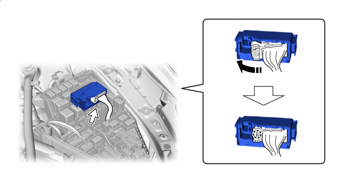

Rotate in this Direction - - Attach the claw and connect the lever connector.
Note:
-
Make sure the connector terminal is free from oil and grease.
-
Do not subject the No. 1 semiconductor power integration ECU to any impact.
-
Do not use a No. 1 semiconductor power integration ECU that has been dropped.
-
Do not disassemble the No. 1 semiconductor power integration ECU.
-
Be sure to connect the lever connector securely.
-
-
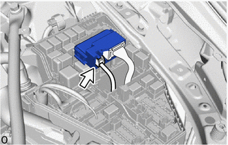
Connect the power source connector.
Note:
-
Make sure the connector terminal is free from oil and grease.
-
Do not subject the No. 1 semiconductor power integration ECU to any impact.
-
Do not use a No. 1 semiconductor power integration ECU that has been dropped.
-
Do not disassemble the No. 1 semiconductor power integration ECU.
-
-
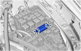
Attach the claw and install the No. 1 semiconductor power integration ECU.
Note:
-
Make sure the connector terminal is free from oil and grease.
-
Do not subject the No. 1 semiconductor power integration ECU to any impact.
-
Do not use a No. 1 semiconductor power integration ECU that has been dropped.
-
Do not disassemble the No. 1 semiconductor power integration ECU.
-
When installing the No. 1 semiconductor power integration ECU to the engine room relay block, do not apply strong impacts to the head of the No. 1 semiconductor power integration ECU.
-
-
- Click here
INSTALL NO. 3 RELAY BLOCK COVER
-
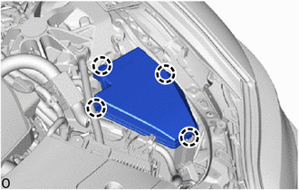
Attach the claw and install the No. 3 relay block cover.
-
- Click here
INSTALL UPPER RADIATOR SUPPORT SEAL
- Click here
CONNECT CABLE TO NEGATIVE AUXILIARY BATTERY TERMINAL
- Click here
INSTALL LUGGAGE COMPARTMENT MAT SUB-ASSEMBLY