| DTC Code | DTC Name |
|---|---|
| C1AB2 | Short to GND in Outer Mirror Indicator(Master) |
DESCRIPTION
This DTC is stored when the blind spot monitor sensor RH detects a short to ground in the outer rear view mirror indicator RH.
| DTC No. | Detection Item | DTC Detection Condition | Trouble Area |
|---|---|---|---|
| C1AB2 | Short to GND in Outer Mirror Indicator(Master) |
|
|
CAUTION / NOTICE / HINT
When checking for DTCs, make sure that the blind spot monitor system is turned on.
PROCEDURE
- Click here
CHECK DTC
-
Turn the power switch off.
-
Turn the power switch on (IG).
-
Recheck for DTCs and check if the same DTC is output again.
- Body Electrical > Blind Spot Monitor Master > Trouble Codes
-
-
OK No DTCs are output. Result Proceed to OK NG
- OK
USE SIMULATION METHOD TO CHECKClick here
- NGClick here
-
- Click here
CHECK HARNESS AND CONNECTOR (BLIND SPOT MONITOR SENSOR RH - FRONT MULTIPLEX NETWORK DOOR ECU RH)
-
Disconnect the L56 blind spot monitor sensor RH connector.
-
Disconnect the H12 front multiplex network door ECU RH connector.
-
Measure the resistance according to the value(s) in the table below.
Standard Resistance Tester Connection Condition Specified Condition L56-4 (OMIR) - Body ground Always 10 kΩ or higher Result Proceed to OK NG
- OKClick here
- NG
REPAIR OR REPLACE HARNESS OR CONNECTOR
-
- Click here
INSPECT OUTER MIRROR ACTUATOR ASSEMBLY RH
-
Disconnect the z37 outer rear view mirror assembly RH connector.
-
Disconnect the IND1 outer mirror RH (outer rear view mirror indicator RH) connector.
-
Measure the resistance according to the value(s) in the table below.
Standard Resistance Tester Connection Condition Specified Condition z37-8 (BSR+) - Body ground Always 10 kΩ or higher Result Proceed to OK NG
- OKClick here
- NG
REPLACE OUTER MIRROR ACTUATOR ASSEMBLY RHClick here
-
- Click here
INSPECT FRONT MULTIPLEX NETWORK DOOR ECU RH
-
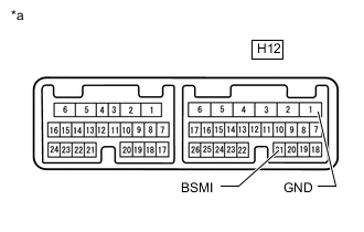
*a Component without harness connected
(Front Multiplex Network Door ECU RH)
Disconnect the front multiplex network door ECU RH connector.
-
Measure the resistance according to the value(s) in the table below.
Standard Resistance Tester Connection Condition Specified Condition H12-21 (BSMI) - H12-1 (GND) Always 10 kΩ or higher Result Proceed to OK NG
- OKClick here
- NG
REPLACE FRONT MULTIPLEX NETWORK DOOR ECU RHClick here
-
- Click here
INSPECT OUTER MIRROR RH (OUTER REAR VIEW MIRROR INDICATOR RH)
-
Remove the outer mirror RH (outer rear view mirror indicator RH).
-
Inspect the outer mirror RH (outer rear view mirror indicator RH).
Result Proceed to OK NG
- OK
REPLACE BLIND SPOT MONITOR SENSOR RHClick here
- NG
REPLACE OUTER MIRROR RH (OUTER REAR VIEW MIRROR INDICATOR RH)Click here
-