CAUTION / NOTICE / HINT
The necessary procedures (adjustment, calibration, initialization or registration) that must be performed after parts are removed, installed or replaced during the side television camera assembly removal/installation are shown below.
| Replacement Part or Procedure | Necessary Procedures | Effects / Inoperative when not Performed | Link |
|---|---|---|---|
|
Side television camera view adjustment | Panoramic view monitor system |
-
Use the same procedure for the RH and LH sides.
-
The procedure listed below is for the LH side.
PROCEDURE
- Click here
REMOVE OUTER REAR VIEW MIRROR ASSEMBLY LH
- Click here
REMOVE OUTER MIRROR LH
- Click here
REMOVE NO. 2 OUTER MIRROR COVER LH
- Click here
REMOVE SIDE TELEVISION CAMERA ASSEMBLY LH
-
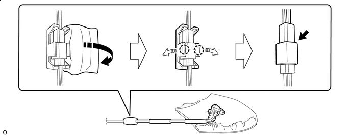

Remove in this Direction 
Direction to Spread the Claw Remove the outer mirror tape.
-
Pull in the direction of the arrow in the claw to remove the camera connector clamp.
-
Disconnect the connector.
-
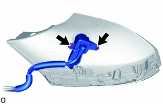
Remove the 2 screws and side television camera assembly LH.
-