TELEMATICS TRANSCEIVER INSTALLATION
PROCEDURE
-
INSTALL TELEMATICS TRANSCEIVER
-
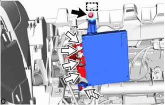

Bolt 
Connector 
Nut Connect the 4 connectors.
-
Attach the guide and temporary install the telematics transceiver.
-
Install the telematics transceiver in the order shown in the illustration.
- Torque:
- 8.0 N*m { 82 kgf*cm, 71 in.*lbf }
-
-
INSTALL GLOVE COMPARTMENT DOOR ASSEMBLY
-
INSTALL GLOVE COMPARTMENT DOOR PAD PLATE
-
INSTALL LOWER NO. 2 INSTRUMENT PANEL AIRBAG ASSEMBLY
-
INSTALL UPPER NO. 2 CONSOLE PANEL GARNISH
-
INSTALL INSTRUMENT CLUSTER FINISH PANEL GARNISH ASSEMBLY
-
INSTALL INSTRUMENT PANEL SAFETY PAD INSERT SUB-ASSEMBLY
-
INSTALL NO. 2 INSTRUMENT PANEL SAFETY PAD SUB-ASSEMBLY
-
INSTALL INSTRUMENT CLUSTER FINISH PANEL GARNISH ASSEMBLY
-
INSTALL NO. 2 INSTRUMENT PANEL UNDER COVER SUB-ASSEMBLY
-
INSTALL LOWER NO. 1 INSTRUMENT PANEL PAD SUB-ASSEMBLY
-
INSTALL INSTRUMENT SIDE PANEL RH
-
INSTALL INSTRUMENT SIDE PANEL LH
-
CONNECT CABLE TO NEGATIVE AUXILIARY BATTERY TERMINAL
Note
When disconnecting the cable, some systems need to be initialized after the cable is reconnected.
-
INSTALL LUGGAGE COMPARTMENT MAT SUB-ASSEMBLY
-
PERFORM DIAGNOSTIC SYSTEM CHECK
-
INSPECT SRS WARNING LIGHT
-
REGISTRATION TELEMATICS TRANSCEIVER