RADIO ANTENNA CORD INSTALLATION
CAUTION / NOTICE / HINT
Tech Tips
-
Use the same procedure for RHD and LHD vehicles.
-
The procedure listed below is for LHD vehicles.
PROCEDURE
-
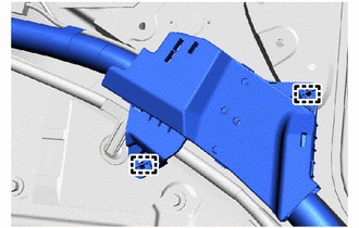
INSTALL NO. 5 ANTENNA CORD SUB-ASSEMBLY
-
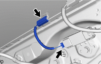
Connect the 2 connectors and install the No. 5 antenna cord sub-assembly.
-
-
INSTALL NO. 2 ANTENNA CORD SUB-ASSEMBLY
-
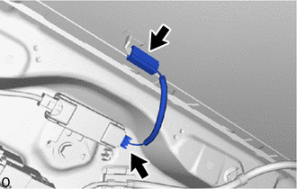
Connect the 2 connectors and install the No. 2 antenna cord sub-assembly.
-
-
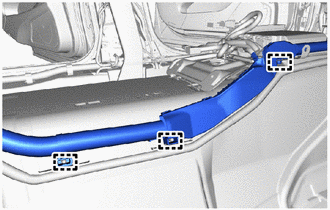
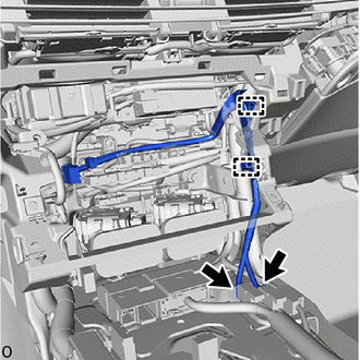
INSTALL ANTENNA CORD SUB-ASSEMBLY
-
except Digital Audio Broadcasting Antenna:
-
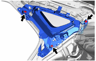
Attach the clamp in area E shown in the illustration to install the antenna cord sub-assembly.
-
Connect the 3 connectors in area E shown in the illustration.
-
Attach the clamp in area D shown in the illustration.
-
Connect the connector in area D shown in the illustration.
-
Attach the clamp in area C shown in the illustration.
-
Connect the connector in area C shown in the illustration.
-
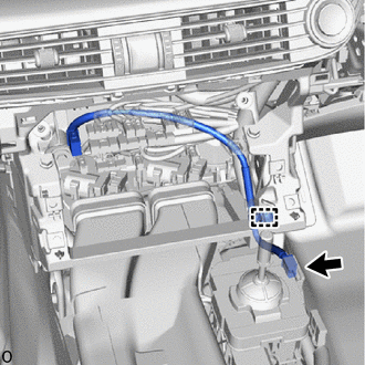
Attach the clamp in area B shown in the illustration.
-
Attach the clamp in area A shown in the illustration.
-
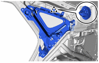
Install the bolt in area A shown in the illustration.
- Torque:
- 8.3 N*m { 85 kgf*cm, 73 in.*lbf }
-
Connect the connector in area A shown in the illustration.
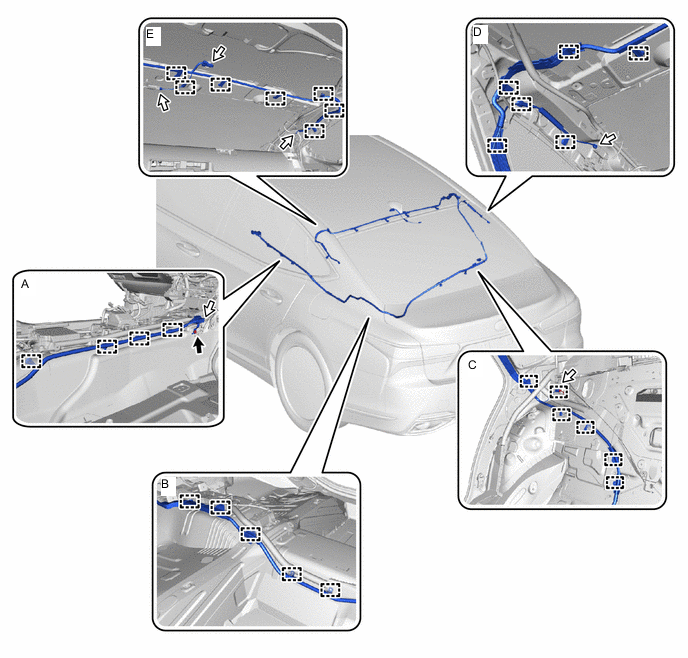

Bolt 
Connector
-
-
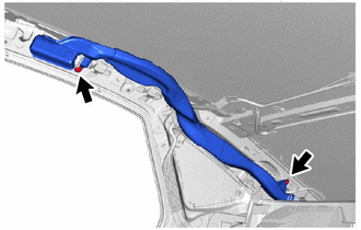
w/ Digital Audio Broadcasting Antenna:
-
Attach the clamp in area E shown in the illustration to install the antenna cord sub-assembly.
-
Connect the 4 connectors in area E shown in the illustration.
-
Attach the clamp in area D shown in the illustration.
-
Connect the 2 connectors in area D shown in the illustration.
-
Attach the clamp in area C shown in the illustration.
-
Connect the connector in area C shown in the illustration.
-
Attach the clamp in area B shown in the illustration.
-
Attach the clamp in area A shown in the illustration.
-
Install the bolt in area A shown in the illustration.
- Torque:
- 8.3 N*m { 85 kgf*cm, 73 in.*lbf }
-
Connect the 2 connectors in area A shown in the illustration.
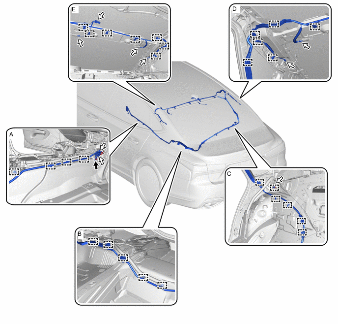
Bolt Connector
-
-
-
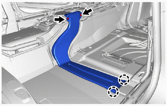
INSTALL FLOOR WIRE
-
Attach the clamp of the wire harness protector to install part of floor wire.
-
Attach the clamp of the wire harness protector to install part of floor wire.
-
-
INSTALL NO. 1 ROOF SIDE AIR DUCT RH (w/ Rear Air Conditioning System)
-
Install the No. 1 roof side air duct RH with the 2 clips.
-
-
INSTALL REAR SIDE WINDOW CURTAIN ASSEMBLY RH
-
w/o Rear Quarter Pillar Shade:
-
Attach the clip to install the rear side window curtain assembly RH.
-
Install the 3 bolts.
-
-
w/ Rear Quarter Pillar Shade:
-
-
INSTALL ROOM PARTITION PAD
-
Return the room partition pad to original position.
-
-
INSTALL CENTER ROOM PARTITION PANEL
-
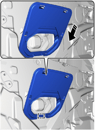

Install in this Direction Attach the guide in the direction of the arrow in the illustration.
-
Attach the claw to install the center room partition panel.
-
-
INSTALL REAR FLOOR SILENCER
-
Install the rear floor silencer with the clip.
-
-
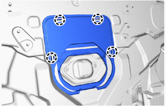
INSTALL NO. 1 FLOOR HEATER AIR DUCT RH
-
Attach the claw to install the No. 1 floor heater air duct RH with the 2 clips.
-
-
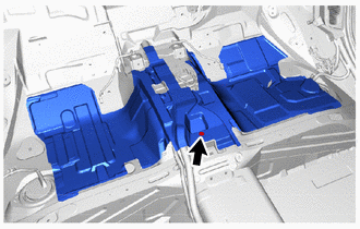
INSTALL FRONT FLOOR CARPET ASSEMBLY
-
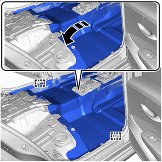
Install in this Direction Install the front floor carpet assembly.
-
Attach the clamp.
-
-
INSTALL NO. 2 EV BATTERY INTAKE DUCT
-
INSTALL REAR SEAT ASSEMBLY
-
for Fixed Seat Type:
-
for Power Seat:
-
-
INSTALL CURTAIN SHIELD AIRBAG ASSEMBLY LH
-
INSTALL CURTAIN SHIELD AIRBAG ASSEMBLY RH
Tech Tips
Use the same procedure described for the LH side.
-
INSTALL NO. 1 CONSOLE BOX DUCT (for LHD)
-
for 2WD:
-
for AWD:
-
-
INSTALL NO. 4 ANTENNA CORD SUB-ASSEMBLY
-
for LHD:
-
Attach the clamp to install the No. 4 antenna cord sub-assembly.
-
Connect the 2 connectors.
-
-
for RHD:
-
Attach the clamp to install the No. 4 antenna cord sub-assembly.
-
Connect the connector.
-
-
-
INSTALL RADIO RECEIVER ASSEMBLY WITH BRACKET
-
CONNECT CABLE TO NEGATIVE AUXILIARY BATTERY TERMINAL
Note
When disconnecting the cable, some systems need to be initialized after the cable is reconnected.
-
INSTALL LUGGAGE COMPARTMENT MAT SUB-ASSEMBLY
-
INSPECT SRS WARNING LIGHT
-
INITIALIZATION OF SEAT ECU
-
PERFORM ZERO POINT CALIBRATION AND SENSITIVITY CHECK (for Front Passenger Side)
-
INSPECT FRONT SEAT ASSEMBLY
-
INSPECT REAR SEAT ASSEMBLY (for Power Seat)
-
INSPECT SEAT HEATER SYSTEM (w/ Seat Heater System)
-
INSPECT CLIMATE CONTROL SEAT SYSTEM (w/ Climate Control Seat System)
-
INSPECT SEAT VIBRATION SYSTEM (w/ Refresh Seat)
-
INSPECT SEAT BELT WARNING SYSTEM
-
w/o Occupant Classification System:
-
w/ Occupant Classification System:
-