CAUTION / NOTICE / HINT
The necessary procedures (adjustment, calibration, initialization, or registration) that must be performed after parts are removed, installed, or replaced during the radio receiver assembly removal/installation are shown below.
| Replacement part or procedure | Necessary procedures | Effects/Inoperative when not performed | Link |
|---|---|---|---|
| Radio receiver assembly | Download necessary data | G-BOOK function |
-
Use the same procedure for RHD and LHD vehicles.
-
The procedure listed below is for LHD vehicles.
PROCEDURE
- Click here
PRECAUTION
Note:
-
After turning the power switch off, waiting time may be required before disconnecting the cable from the negative (-) auxiliary battery terminal. Therefore, make sure to read the disconnecting the cable from the negative (-) auxiliary battery terminal notices before proceeding with work.
-
- Click here
REMOVE CONSOLE BOX ASSEMBLY
- Click here
REMOVE INSTRUMENT SIDE PANEL LH
-
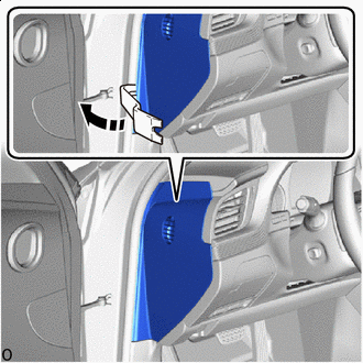

Remove in this Direction Insert moulding remover B as shown in the illustration and push in the direction indicated by the arrow to slightly pull the bottom part of the instrument side panel LH away from the vehicle.
-
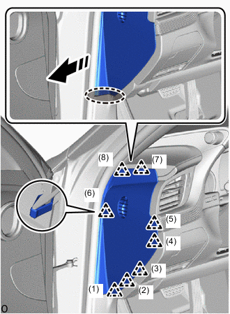

Place Hands Here Remove in this Direction Place your hand at the position shown in the illustration, detach the clip in the removal order and remove the instrument side panel LH.
-
- Click here
REMOVE INSTRUMENT SIDE PANEL RH
-
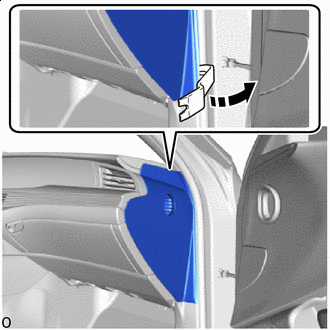
Remove in this Direction Insert moulding remover B as shown in the illustration and push in the direction indicated by the arrow to slightly pull the bottom part of the instrument side panel RH away from the vehicle.
-
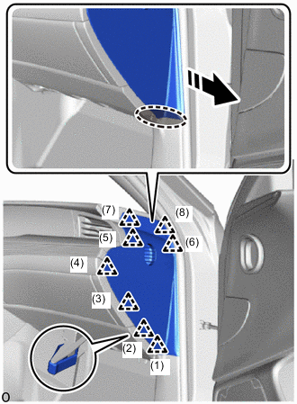
Place Hands Here Remove in this Direction Place your hand at the position shown in the illustration, detach the clip in the removal order and remove the instrument side panel RH.
-
- Click here
REMOVE LOWER NO. 1 INSTRUMENT PANEL PAD SUB-ASSEMBLY
- Click here
REMOVE LOWER INSTRUMENT PANEL FINISH PANEL ASSEMBLY
- Click here
REMOVE RADIO RECEIVER ASSEMBLY WITH BRACKET
-
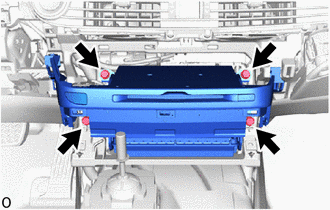
Remove the 4 bolts.
-
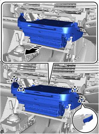
Remove in this Direction Pull the radio receiver assembly with bracket out toward the rear of the vehicle.
-
Disconnect each connector and remove the radio receiver assembly with bracket.
-
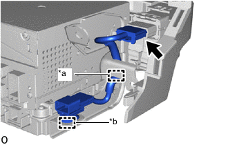
*a Guide *b Clamp Disconnect the connector.
-
Detach the clamp and guide and remove the switch wire.
-
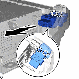
Remove in this Direction Detach the claw and remove the brake hold switch.
-
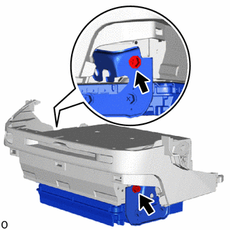
Remove the 2 screws and navigation ECU assembly with bracket from the radio receiver assembly.
-
- Click here
REMOVE NO. 1 NAVIGATION WIRE
- Click here
REMOVE NO. 1 RADIO RECEIVER BRACKET
-
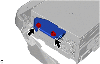
Remove the 2 screws and No. 1 radio receiver bracket.
-
- Click here
REMOVE NO. 2 RADIO RECEIVER BRACKET
-
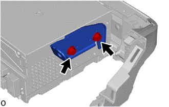
Remove the 2 screws and No. 2 radio receiver bracket.
-
- Click here
REMOVE RADIO RECEIVER ASSEMBLY