| DTC Code | DTC Name |
|---|---|
| B1533 | GVIF Disconnected (from RSE to Seatback Display RH) |
| B1534 | GVIF Disconnected (from RSE to Seatback Display LH) |
DESCRIPTION
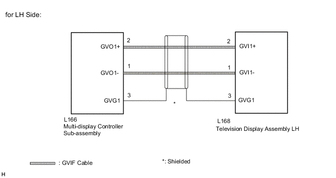
The television display assembly and multi-display controller sub-assembly are connected by GVIF cable.
When a GVIF cable error occurs between the multi-media module receiver assembly and multi-display controller sub-assembly, this DTCs will be stored.
| DTC No. | Detection Item | DTC Detection Condition | Trouble Area |
|---|---|---|---|
| B1533 | GVIF Disconnected (from RSE to Seatback Display RH) | GVIF disconnected (from multi-display controller sub-assembly to television display assembly RH) |
|
| B1534 | GVIF Disconnected (from RSE to Seatback Display LH) | GVIF disconnected (from multi-display controller sub-assembly to television display assembly LH) |
|
CAUTION / NOTICE / HINT
The following malfunctions may occur if a radio receiver assembly from another vehicle is installed to this vehicle. Therefore, when replacing the radio receiver assembly, be sure to replace it with new one.
-
Communication malfunction DTC is output
-
Does not operate normally
Depending on the parts that are replaced during vehicle inspection or maintenance, performing initialization, registration or calibration may be needed. Refer to Precaution for Navigation System.
PROCEDURE
- Click here
CLEAR DTC
-
Clear the DTCs.
- Body Electrical > Navigation System > Clear DTCs
-
-
Result Proceed to NEXT
- NEXTClick here
-
- Click here
CHECK FOR DTC
-
Check for DTCs.
- Body Electrical > Navigation System > Trouble Codes
-
-
Result Result Proceed to DTC B1533 and B1534 are not output. A DTC B1533 is output. B DTC B1534 is output. C
- A
USE SIMULATION METHOD TO CHECKClick here
- BClick here
- CClick here
-
- Click here
CHECK HARNESS AND CONNECTOR (GVIF CABLE)
-
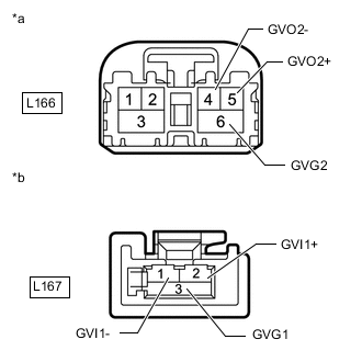
*a GVIF Cable
(to Multi-display Controller Sub-assembly)
*b GVIF Cable
(to Television Display Assembly RH)
Disconnect the multi-display controller sub-assembly connector.
-
Disconnect the television display assembly RH connector.
-
Measure the resistance according to the value(s) in the table below.
Standard Resistance Tester Connection Condition Specified Condition L166-4 (GVO2-) - L167-1 (GVI1-) Always Below 1 Ω L166-5 (GVO2+) - L167-2 (GVI1+) Always Below 1 Ω L166-6 (GVG2) - L167-3 (GVG1) Always Below 1 Ω L166-4 (GVO2-) - Body ground Always 10 kΩ or higher L166-5 (GVO2+) - Body ground Always 10 kΩ or higher L166-6 (GVG2) - Body ground Always 10 kΩ or higher Result Proceed to OK NG
- OKClick here
- NG
REPLACE HARNESS OR CONNECTOR (GVIF CABLE)
-
- Click here
REPLACE TELEVISION DISPLAY ASSEMBLY RH
-
Replace the television display assembly RH with a new or known good one.
Result Proceed to NEXT
- NEXTClick here
-
- Click here
CLEAR DTC
-
Clear the DTCs.
- Body Electrical > Navigation System > Clear DTCs
-
-
Result Proceed to NEXT
- NEXTClick here
-
- Click here
CHECK FOR DTC
-
Check for DTCs.
- Body Electrical > Navigation System > Trouble Codes
-
-
OK DTC B1533 is not output. Result Proceed to OK NG
- OK
END (TELEVISION DISPLAY ASSEMBLY RH IS DEFECTIVE)
- NG
REPLACE MULTI-DISPLAY CONTROLLER SUB-ASSEMBLYClick here
-
- Click here
CHECK HARNESS AND CONNECTOR (GVIF CABLE)
-
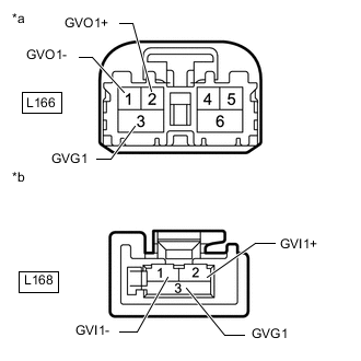
*a GVIF Cable
(to Multi-display Controller Sub-assembly)
*b GVIF Cable
(to Television Display Assembly LH)
Disconnect the multi-display controller sub-assembly connector.
-
Disconnect the television display assembly LH connector.
-
Measure the resistance according to the value(s) in the table below.
Standard Resistance Tester Connection Condition Specified Condition L166-1 (GVO1-) - L168-1 (GVI1-) Always Below 1 Ω L166-2 (GVO1+) - L168-2 (GVI1+) Always Below 1 Ω L166-3 (GVG1) - L168-3 (GVG1) Always Below 1 Ω L166-1 (GVO1-) - Body ground Always 10 kΩ or higher L166-2 (GVO1+) - Body ground Always 10 kΩ or higher L166-3 (GVG1) - Body ground Always 10 kΩ or higher Result Proceed to OK NG
- OKClick here
- NG
REPLACE HARNESS OR CONNECTOR (GVIF CABLE)
-
- Click here
REPLACE TELEVISION DISPLAY ASSEMBLY LH
-
Replace the television display assembly LH with a new or known good one.
Result Proceed to NEXT
- NEXTClick here
-
- Click here
CLEAR DTC
-
Clear the DTCs.
- Body Electrical > Navigation System > Clear DTCs
-
-
Result Proceed to NEXT
- NEXTClick here
-
- Click here
CHECK FOR DTC
-
Check for DTCs.
- Body Electrical > Navigation System > Trouble Codes
-
-
OK DTC B1534 is not output. Result Proceed to OK NG
- OK
END (TELEVISION DISPLAY ASSEMBLY LH IS DEFECTIVE)
- NG
REPLACE MULTI-DISPLAY CONTROLLER SUB-ASSEMBLYClick here
-