STEERING COLUMN ASSEMBLY REMOVAL

CAUTION / NOTICE / HINT
The necessary procedures (adjustment, calibration, initialization, or registration) that must be performed after parts are removed, installed, or replaced during the steering column assembly removal/installation are shown below.
| Replacement Part or Procedure | Necessary Procedure | Effect/Inoperative when not Performed | Link |
|---|---|---|---|
| Disconnect cable from negative auxiliary battery terminal | Memorize steering angle neutral point | LKA/LDA system (for Mono camera type) | for Stereo Camera type: Click here for Mono Camera type: Click here |
| Lane control system (for Stereo camera type) | |||
| Parking support brake system* | |||
| Pre-collision system (for Mono camera type) | |||
| Pre-collision system (for Stereo camera type) | |||
| Adaptive high beam system | |||
Lighting system (EXT) |
|||
| Variable gear ratio steering system | |||
| Parking assist monitor system | |||
| Panoramic view monitor system | |||
| Initialize rear door sunshade system | Rear door sunshade system | ||
| Initialize power trunk lid system | Power trunk lid system | ||
| Steering sensor (Including removal and installation) | Steering angle neutral point | Parking support brake system | |
| Parking assist monitor system | |||
| Panoramic view monitor system | |||
| Steering angle setting | Parking assist monitor system | ||
| Panoramic view monitor system | |||
|
Perform actuator angle neutral point calibration and initialization |
|
Click here Click here
Tech Tips
-
Use the same procedure for RHD and LHD vehicles.
-
The procedure listed below is for LHD vehicles.
PROCEDURE
-
PRECAUTION
-
CUSTOMIZE POWER TILT AND POWER TELESCOPIC STEERING COLUMN SYSTEM
-
Disable the auto tilt away function by changing the customize settings.
Note
Record the current customize setting (whether the auto tilt away function is enabled or disabled) in order to restore the current setting after finishing the operation.
Tech Tips
Performing the above operation causes the auto tilt away function to be disabled when the power switch is turned off.
-
Turn the power switch on (IG). Operate the tilt and telescopic switch to fully extend and lower the steering column assembly.
-
-
ALIGN FRONT WHEELS FACING STRAIGHT AHEAD
-
AIR SUSPENSION CONTROL PROHIBITED (w/ Air Suspension)
-
REMOVE HORN BUTTON ASSEMBLY
-
REMOVE STEERING WHEEL ASSEMBLY
-
REMOVE LOWER STEERING COLUMN COVER
-
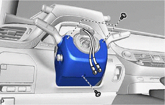
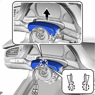
Remove the 3 screws.
-
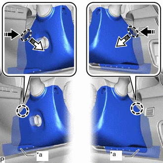
*a Felt 
Push Area 
Remove in this Direction (1) 
Remove in this Direction (2) Press in, in the direction shown by the arrow (1) in the illustration, and disengage the claws.
-
Pull out in the direction indicated by the arrow (2) in the illustration, disengage the claws to remove the lower steering column cover.
Note
Do not damage the felt.
-
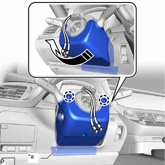
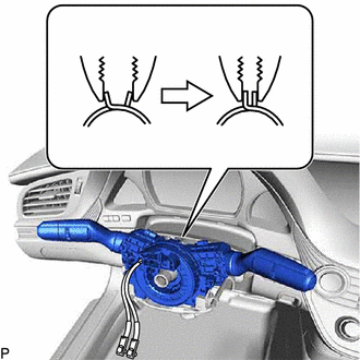
*a Felt Remove in this Direction Disengage the 2 claws.
-
Pull in the direction indicated by the arrow to remove the lower steering column cover.
Note
Do not damage the tilt and telescopic switch and felt.
-
-
REMOVE UPPER STEERING COLUMN COVER
-
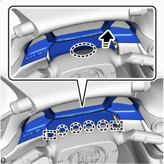
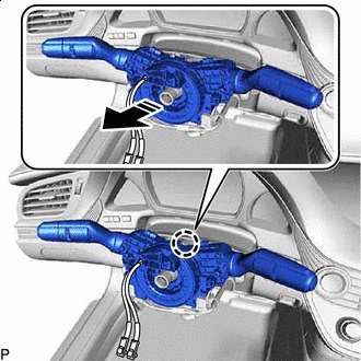
Place Hand Here Remove in this Direction Detach the claws and guides as shown in the illustration.
-
Remove in this Direction Disengage the claw to remove the upper steering column cover.
-
-
REMOVE TURN SIGNAL SWITCH ASSEMBLY WITH SPIRAL CABLE SUB-ASSEMBLY
Note
-
Do not replace the spiral cable with sensor sub-assembly with the battery connected and the power switch on (IG).
-
Do not rotate the spiral cable with sensor sub-assembly without the steering wheel assembly installed, with the battery connected and the power switch on (IG).
-
Ensure that the steering wheel assembly is installed and aligned straight when inspecting the steering sensor.
-
Disconnect each connector from the turn signal switch assembly with spiral cable sub-assembly.
-
Using pliers, support the band clamp while loosened.
-
Remove in this Direction Disengage the claw to remove the turn signal switch assembly with spiral cable sub-assembly from the steering column assembly.
-
-
REMOVE LOWER NO. 1 INSTRUMENT PANEL AIR BAG ASSEMBLY
-
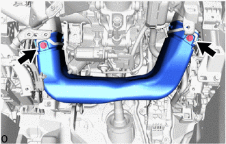
REMOVE NO. 1 AIR DUCT SUB-ASSEMBLY
-
Remove in this Direction Remove the 2 bolts and No. 1 air duct sub-assembly in the direction of the arrow shown in the illustration.
-
-
REMOVE NO. 1 HEATER TO REGISTER DUCT
-
Remove the 2 screws and No. 1 heater to register duct.
-
-
REMOVE STEERING COLUMN ASSEMBLY
-
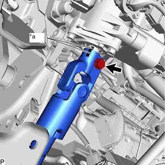
w/o VGRS for 2WD:
-
*a Matchmark Put matchmarks on the No. 2 steering intermediate shaft assembly and steering column assembly.
-
Remove the bolt.
-
-
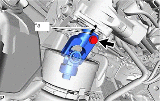
*a Matchmark for AWD:
-
Put matchmarks on the No. 2 steering intermediate shaft assembly and steering column assembly.
-
Remove the bolt.
-
-
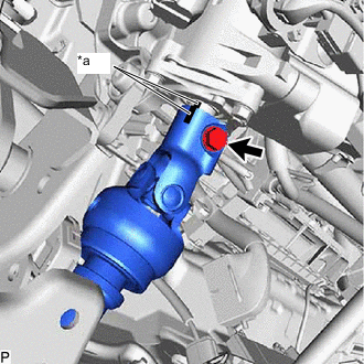
w/ VGRS:
-
*a Matchmark Put matchmarks on the steering actuator assembly and steering column assembly.
-
Remove the bolt.
-
-
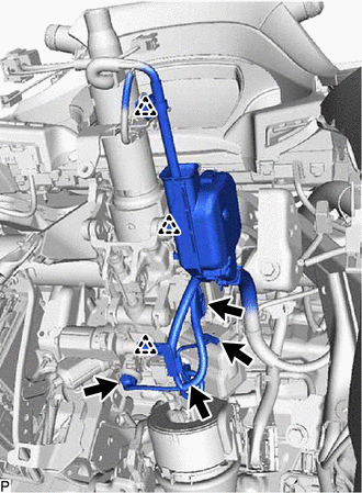
Disconnect each connector and disengage each wire harness clamp from the steering column assembly.
-
Remove the 2 nuts, bolt and steering column assembly.
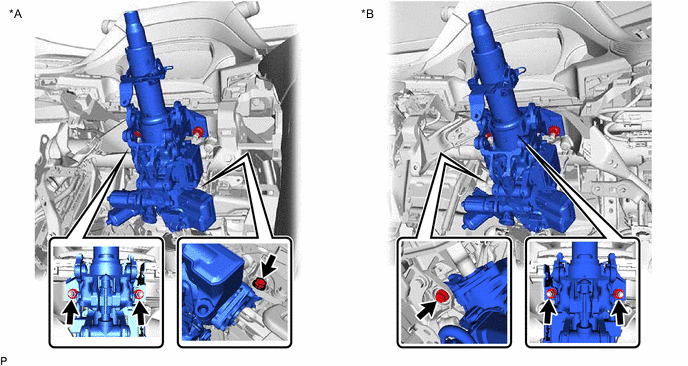
*A for LHD *B for RHD -
w/o VGRS:
-
Separate the steering column assembly from the No. 2 steering intermediate shaft assembly.
-
-
w/ VGRS:
-
Separate the steering column assembly from the steering actuator assembly.
-
-
-
REMOVE TRANSMISSION UNDER COVER (for 2WD)
-
REMOVE NO. 2 ENGINE UNDER COVER ASSEMBLY (for 2WD)
-
REMOVE FRONT WHEEL LH (for AWD)
-
REMOVE NO. 2 STEERING INTERMEDIATE SHAFT ASSEMBLY (w/o VGRS for 2WD)
-
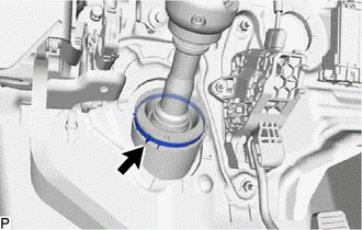
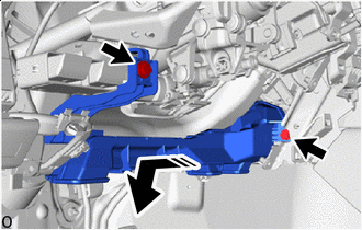
Loosen the clamp.
-
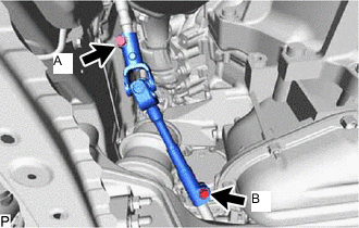
Loosen the bolt (A).
Note
Do not remove the bolt (A).
-
Remove the bolt (B).
-
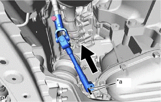
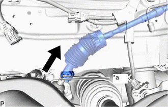
*a Matchmark Slide the steering sliding with shaft yoke sub-assembly and put matchmarks on the steering sliding with shaft yoke sub-assembly and rack and pinion power steering gear assembly.
-
Separate the steering sliding with shaft yoke sub-assembly from the rack and pinion power steering gear assembly.
-
Remove the steering sliding with shaft yoke sub-assembly with the No. 2 steering intermediate shaft assembly from the vehicle.
-
-
REMOVE NO. 2 STEERING INTERMEDIATE SHAFT ASSEMBLY (for AWD)
-
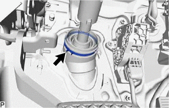
Loosen the clamp.
-

Remove the bolt.
-
*a Matchmark Slide the No. 2 steering intermediate shaft assembly and put matchmarks on the No. 2 steering intermediate shaft assembly and rack and pinion power steering gear assembly.
-
Remove the No. 2 steering intermediate shaft assembly from the vehicle.
-
-
REMOVE STEERING ACTUATOR ASSEMBLY (w/ VGRS)
-
REMOVE STEERING SLIDING WITH SHAFT YOKE SUB-ASSEMBLY (for 2WD)
-
w/o VGRS:
-
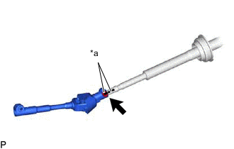
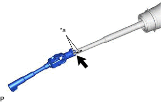
*a Matchmark Put matchmarks on the steering sliding yoke sub-assembly and No. 2 steering intermediate shaft assembly.
-
Remove the bolt.
-
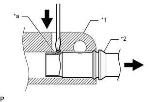
*1 Steering Sliding Yoke with Shaft Sub-assembly *2 No. 2 Steering Intermediate Shaft Assembly *a Claw Using a screwdriver, disengage the claw and remove the steering sliding yoke sub-assembly from the No. 2 steering intermediate shaft assembly.
Tech Tips
Even if the claw is broken, the No. 2 steering intermediate shaft assembly can be reused if the claw is removed.
-
-
w/ VGRS:
-
*a Matchmark Put matchmarks on the steering sliding yoke sub-assembly and steering actuator assembly.
-
Remove the bolt.
-
*1 Steering Sliding Yoke with Shaft Sub-assembly *2 Steering Actuator Assembly *a Claw Using a screwdriver, disengage the claw and remove the steering sliding yoke sub-assembly from the steering actuator assembly.
-
-