ELECTRIC PARKING BRAKE SYSTEM, Diagnostic DTC:C13A2
| DTC Code | DTC Name |
|---|---|
| C13A2 | Engine Switch/Power Switch Malfunction |
DESCRIPTION
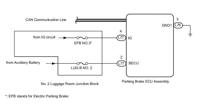
Power is supplied to the parking brake ECU assembly from the BECU terminal.
C13A2 is stored if the IG power source is not input to the parking brake ECU assembly when communication with other ECUs occurs.
| DTC No. | Detection Item | DTC Detection Condition | Trouble Area | Memory | Note |
|---|---|---|---|---|---|
| C13A2 | Engine Switch/Power Switch Malfunction |
|
|
Yes | An electric parking brake system malfunction is displayed on the multi-information display. |
WIRING DIAGRAM
CAUTION / NOTICE / HINT
Note
-
Inspect the fuses for circuits related to this system before performing the following inspection procedure.
-
The electric parking brake may still operate up to 20 seconds after the power switch is turned off. Before disconnecting connectors or fuses, turn the power switch off and wait 20 seconds or more.
-
If the parking brake ECU assembly or parking brake with bracket actuator assembly is replaced, perform the "Reset Memory" and "Acquire Tension Sensor Zero Point" procedures.
PROCEDURE
-
CHECK HARNESS AND CONNECTOR (PARKING BRAKE ECU ASSEMBLY - IG POWER SOURCE CIRCUIT)
-
Turn the power switch off.
-
Disconnect the parking brake ECU assembly connector.
-
Turn the power switch on (IG).
-
Measure the voltage according to the value(s) in the table below.
Standard Voltage Tester Connection Switch Condition Specified Condition L77-4 (IG) - Body ground Power switch on (IG) 11 to 14 V Result Proceed to OK NG
NG 
REPAIR IG POWER SOURCE CIRCUIT
OK 
-
-
CHECK DTC
-
Clear the DTCs.
Chassis > Electric Parking Brake > Clear DTCs -
Turn the power switch off.
-
Check for DTCs.
Chassis > Electric Parking Brake > Trouble CodesResult Result Proceed to DTC is output A DTC is not output B
A
REPLACE PARKING BRAKE ECU ASSEMBLY Click here
B
USE SIMULATION METHOD TO CHECK Click here
-