ELECTRIC PARKING BRAKE SYSTEM, Diagnostic DTC:C13A3, C13AB
| DTC Code | DTC Name |
|---|---|
| C13A3 | Open or Short Circuit in Lock Switch Circuit |
| C13AB | Lock Switch Circuit Comparison |
DESCRIPTION
When the electric parking brake switch assembly is pushed to the lock side, a lock request signal is output to the parking brake ECU assembly.
| DTC No. | Detection Item | DTC Detection Condition | Trouble Area | Memory | Note |
|---|---|---|---|---|---|
| C13A3 | Open or Short Circuit in Lock Switch Circuit |
Detection Condition 1:
Detection Condition 2: Tech Tips *: This value is based on the assumption that the BECU terminal voltage is 11 V. The threshold changes according to the BECU terminal voltage. For details, refer to "Threshold Changes According to BECU Terminal Voltage". |
|
Yes | An electric parking brake system malfunction is displayed on the multi-information display. |
| C13AB | Lock Switch Circuit Comparison |
|
|
Yes | An electric parking brake system malfunction is displayed on the multi-information display. |
| Vehicle Condition | |||||
| Pattern 1 | Pattern 2 | Pattern 3 | Pattern 4 | ||
| Diagnosis Condition | Electric parking brake switch assembly is operated to lock side with power switch off | ○ | ○ | - | - |
| Power switch on (IG) | - | - | ○ | ○ | |
| Malfunction Status | LCK1 terminal voltage is below 2.3 V | ○ | - | ○ | - |
| LCK1 terminal voltage is 4.35 V or more | - | ○ | - | ○ | |
| Detection Time | Approximately 1 second | Approximately 1 second | Approximately 1 second | Approximately 1 second | |
| Trip Count | 1 trip | 1 trip | 1 trip | 1 trip | |
Tech Tips
If the conditions match either of these patterns, a DTC will be output.
| Vehicle Condition | |||||
| Pattern 5 | Pattern 6 | Pattern 7 | Pattern 8 | ||
| Diagnosis Condition | Electric parking brake switch assembly is operated to lock side with power switch off | ○ | ○ | - | - |
| Power switch on (IG) | - | - | ○ | ○ | |
| Malfunction Status | LCK2 terminal voltage is below 1.4 V (*) | ○ | - | ○ | - |
| LCK2 terminal voltage is above 9 V (*) | - | ○ | - | ○ | |
| Detection Time | Approximately 1 second | Approximately 1 second | Approximately 1 second | Approximately 1 second | |
| Trip Count | 1 trip | 1 trip | 1 trip | 1 trip | |
Tech Tips
-
If the conditions match either of these patterns, a DTC will be output.
-
*: This value is based on the assumption that the BECU terminal voltage is 11 V.
The threshold changes according to the BECU terminal voltage.
For details, refer to "Threshold Changes According to BECU Terminal Voltage".
Figure 1. Threshold Changes According to BECU Terminal Voltage
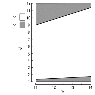
| *a | BECU Terminal Voltage (V) |
| *b | LCK2 Terminal Voltage (V) |
| *c | Normal Range |
| *d | DTC Detection Range |
| Vehicle Condition | |||
| Pattern 1 | Pattern 2 | ||
| Diagnosis Condition | Electric parking brake switch assembly is operated to lock side with power switch off | ○ | - |
| Power switch on (IG) | - | ○ | |
| Malfunction Status | Lock 1 switch and lock 2 switch ON/OFF evaluations do not match | ○ | ○ |
| Detection Time | Repeats 5 times | Repeats 5 times | |
| Trip Count | 1 trip | 1 trip | |
Tech Tips
If the conditions match either of these patterns, a DTC will be output.
WIRING DIAGRAM
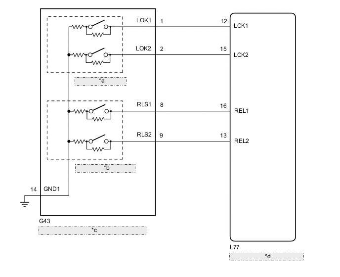
| *a | Lock Switch (Push) |
| *b | Release Switch (Pull) |
| *c | Electric Parking Brake Switch Assembly |
| *d | Parking Brake ECU Assembly |
CAUTION / NOTICE / HINT
Note
-
The electric parking brake may still operate up to 20 seconds after the power switch is turned off. Before disconnecting connectors or fuses, turn the power switch off and wait 20 seconds or more.
-
When the electric parking brake switch assembly is pushed and held for 1 second or more without being pushed fully to the lock side, one of the 2 linked contacts may turn on while the other one turns off causing this DTC to be stored.
-
If the parking brake ECU assembly is replaced, perform the "Reset Memory" and "Acquire Tension Sensor Zero Point" procedures.
PROCEDURE
-
INSPECT ELECTRIC PARKING BRAKE SWITCH ASSEMBLY
-
Inspect the electric parking brake switch assembly.
Result Proceed to OK NG
NG 
REPLACE ELECTRIC PARKING BRAKE SWITCH ASSEMBLY Click here
OK 
-
-
CHECK HARNESS AND CONNECTOR (PARKING BRAKE ECU ASSEMBLY - ELECTRIC PARKING BRAKE SWITCH ASSEMBLY)
-
Turn the power switch off.
-
Disconnect the G43 electric parking brake switch assembly connector.
-
Disconnect the L77 parking brake ECU assembly connector.
-
Measure the resistance according to the value(s) in the table below.
Standard Resistance Tester Connection Condition Specified Condition L77-12 (LCK1) - G43-1 (LOK1) Always Below 5 Ω L77-15 (LCK2) - G43-2 (LOK2) Always Below 5 Ω L77-12 (LCK1) or G43-1 (LOK1) - Body ground Always 10 kΩ or higher L77-15 (LCK2) or G43-2 (LOK2) - Body ground Always 10 kΩ or higher G43-14 (GND1) - Body ground Always Below 5 Ω Result Proceed to OK NG
NG
REPAIR OR REPLACE HARNESS OR CONNECTOR
OK
-
-
CHECK DTC
-
Clear the DTCs.
Chassis > Electric Parking Brake > Clear DTCs -
Turn the power switch off.
-
Turn the power switch on (IG).
-
Perform a lock operation with the electric parking brake switch assembly.
Tech Tips
When the electric parking brake switch assembly is pushed and held for 1 second or more without being pushed fully to the lock side, one of the 2 linked contacts may turn on while the other one turns off causing this DTC to be stored.
-
Check for DTCs.
Chassis > Electric Parking Brake > Trouble CodesResult Result Proceed to DTC is output A DTC is not output B
A
REPLACE PARKING BRAKE ECU ASSEMBLY Click here
B
USE SIMULATION METHOD TO CHECK Click here
-