PROCEDURE
- Click here
INSTALL MASTER CYLINDER PUSH ROD CLEVIS
-
Temporarily install the lock nut and master cylinder push rod clevis to the brake master cylinder assembly.
Note:Tighten the lock nut when adjusting the brake pedal height.
-
- Click here
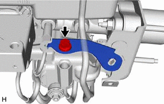
INSTALL BRAKE STROKE SIMULATOR BRACKET
-
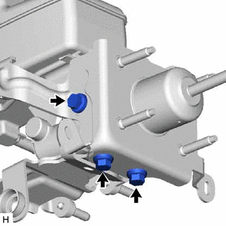
Install the brake stroke simulator bracket to the brake master cylinder sub-assembly with the 3 bolts.
19 N*m 194 kgf*cm 14 ft.*lbf
-
- Click here
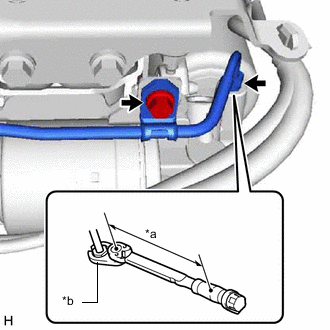
INSTALL NO. 1 BRAKE ACTUATOR TUBE
-
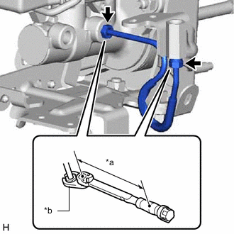
*a Torque Wrench Fulcrum Length *b Union Nut Wrench Using a union nut wrench, connect the No. 1 brake actuator tube to the brake master cylinder sub-assembly.
Specified tightening torque 15.2 N*m 155 kgf*cm 11 ft.*lbf Note:
-
Do not kink or damage the No. 1 brake actuator tube.
-
Do not allow any foreign matter such as dirt or dust to enter the No. 1 brake actuator tube from the connecting parts.
Tip:
-
Calculate the torque wrench reading when changing the fulcrum length of the torque wrench.
-
When using a union nut wrench (fulcrum length of 22 mm (0.8661 in.)) + torque wrench (fulcrum length of 162 mm (6.3779 in.)): 13.4 N*m (137 kgf*cm, 10 ft.*lbf)
-
-
- Click here
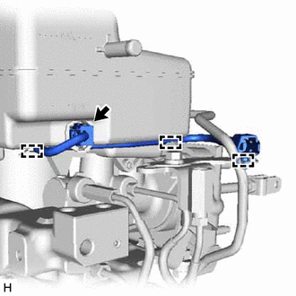
INSTALL BRAKE MASTER CYLINDER TUBE
-
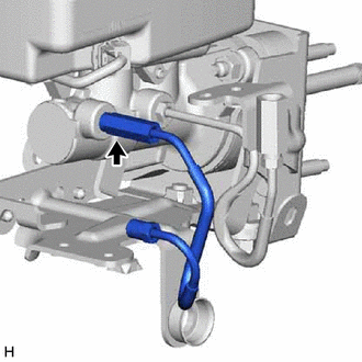
Temporarily install the brake master cylinder tube to the brake master cylinder sub-assembly.
-
- Click here
INSTALL BRAKE STROKE SIMULATOR CYLINDER SUB-ASSEMBLY
-
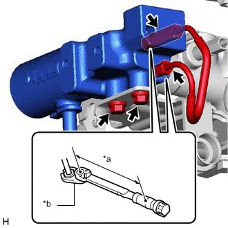
*a Torque Wrench Fulcrum Length *b Union Nut Wrench Install the brake stroke simulator cylinder sub-assembly to the brake stroke simulator bracket with the 2 bolts.
8.0 N*m 82 kgf*cm 71 in.*lbf -
Temporarily install the brake master cylinder tube to the brake master cylinder sub-assembly.
-
Using a union nut wrench, tighten the brake master cylinder tube.
Specified tightening torque 15.2 N*m 155 kgf*cm 11 ft.*lbf Note:
-
Do not kink or damage the brake master cylinder tube.
-
Do not allow any foreign matter such as dirt or dust to enter the brake master cylinder tube from the connecting parts.
Tip:
-
Calculate the torque wrench reading when changing the fulcrum length of the torque wrench.
-
When using a union nut wrench (fulcrum length of 22 mm (0.8661 in.)) + torque wrench (fulcrum length of 162 mm (6.3779 in.)): 13.4 N*m (137 kgf*cm, 10 ft.*lbf)
-
-
- Click here
INSTALL MASTER CYLINDER RESERVOIR GROMMET
-
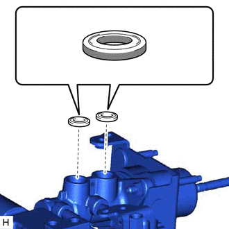

Lithium Soap Base Glycol Grease Apply a light coat of lithium soap base glycol grease to the entire circumference of 2 new master cylinder reservoir grommets.
-
Install the 2 master cylinder reservoir grommets to the brake master cylinder body.
-
- Click here
INSTALL BRAKE MASTER CYLINDER RESERVOIR STRAINER
- Click here
INSTALL BRAKE MASTER CYLINDER RESERVOIR FILLER CAP ASSEMBLY
- Click here
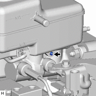
INSTALL BRAKE MASTER CYLINDER RESERVOIR ASSEMBLY
-
Secure the brake master cylinder in a vise.
Note:Place aluminum plates on the vise to prevent damage to the brake master cylinder.
-
Install the brake master cylinder reservoir assembly to the brake master cylinder body.
-
Using a pin punch and hammer, install a pin to the brake master cylinder reservoir assembly.
-
- Click here
INSTALL NO. 1 BRAKE ACTUATOR BRACKET
-
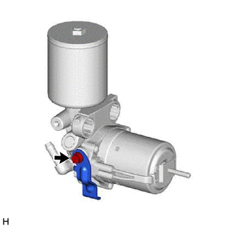
Install the No. 1 brake actuator bracket to the brake booster with accumulator pump assembly with the bolt.
8.0 N*m 82 kgf*cm 71 in.*lbf
-
- Click here
INSTALL TUBE CLAMP BRACKET
-
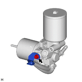
Install the tube clamp bracket to the brake booster with accumulator pump assembly with the bolt.
8.0 N*m 82 kgf*cm 71 in.*lbf
-
- Click here
INSTALL BRAKE BOOSTER WITH ACCUMULATOR PUMP ASSEMBLY
-
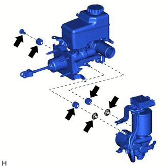
Install the brake booster pump bush and brake booster pump collar to the brake stroke simulator bracket.
-
Install the 2 brake booster pump bushes and 2 brake booster pump collars to the brake booster with accumulator pump assembly.
-
Install the brake booster with accumulator pump assembly to the brake master with stroke simulator cylinder assembly with the nut.
5.4 N*m 55 kgf*cm 48 in.*lbf -
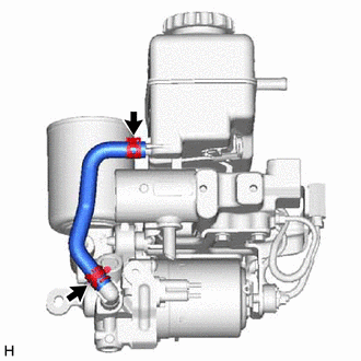
Connect the No. 2 brake actuator hose to the brake booster with accumulator pump assembly, brake master cylinder reservoir assembly and slide the clamp to secureit.
-
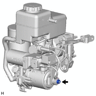
Install the brake actuator case with the bolt.
8.0 N*m 82 kgf*cm 71 in.*lbf -
Attach the clip.
-
- Click here
INSTALL NO. 2 BRAKE ACTUATOR TUBE
-
*a Torque Wrench Fulcrum Length *b Union Nut Wrench Temporarily install the No. 2 brake actuator tube to the brake booster with accumulator pump assembly.
Note:
-
Do not kink or damage the No. 2 brake actuator tube.
-
Do not allow any foreign matter such as dirt or dust to enter the No. 2 brake actuator tube from the connecting parts.
-
-
Install the tube clamp with the bolt.
8.0 N*m 82 kgf*cm 71 in.*lbf -
Using a union nut wrench, tighten the No. 2 brake actuator tube.
Specified tightening torque 15.2 N*m 155 kgf*cm 11 ft.*lbf Note:
-
Do not kink or damage the No. 2 brake actuator tube.
-
Do not allow any foreign matter such as dirt or dust to enter the No. 2 brake actuator tube from the connecting parts.
Tip:
-
Calculate the torque wrench reading when changing the fulcrum length of the torque wrench.
-
When using a union nut wrench (fulcrum length of 22 mm (0.8661 in.)) + torque wrench (fulcrum length of 162 mm (6.3779 in.)): 13.4 N*m (137 kgf*cm, 10 ft.*lbf)
-
-
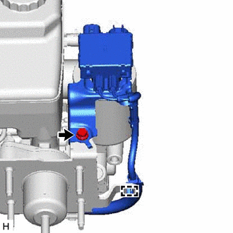
- Click here
INSTALL RESERVOIR BRACKET
-
Install the reservoir bracket to the brake master with stroke simulator cylinder assembly with the bolt.
8.0 N*m 82 kgf*cm 71 in.*lbf -
Connect the connector.
-
Attach the 2 claws to connect the wire harness to the brake master cylinder reservoir assembly.
-
Attach the connector clamp.
-