BRAKE MASTER CYLINDER(for RHD) REMOVAL
CAUTION / NOTICE / HINT
The necessary procedures (adjustment, calibration, initialization, or registration) that must be performed after parts are removed, installed, or replaced during brake master cylinder sub-assembly removal/installation are shown below.
| Replaced Part or Performed Procedure | Necessary Procedure | Effect/Inoperative Function when Necessary Procedure not Performed | Link |
|---|---|---|---|
| Auxiliary battery terminal is disconnected/reconnected | Memorize steering angle neutral point | LKA/LDA system (for Mono camera type) | for Stereo Camera type: Click here for Mono Camera type: Click here |
| Lane control system (for Stereo camera type) | |||
| Parking support brake system* | |||
| Pre-collision system (for Stereo camera type) | |||
| Pre-collision system (for Mono camera type) | |||
| Adaptive high beam system | |||
Lighting system (EXT) |
|||
| Variable gear ratio steering system | |||
| Parking assist monitor system | |||
| Panoramic view monitor system | |||
| Initialize rear door sunshade system | Rear door sunshade system | ||
| Initialize power trunk lid system | Power trunk lid system | ||
| Brake pedal support assembly (Including removal and installation) |
|
|
for Initialization: Click here for Calibration: Click here |
| Brake actuator assembly (Including removal and installation) |
|
Click here Click here
CAUTION / NOTICE / HINT
Note
While the auxiliary battery is connected, even if the power switch is off, the brake control system activates when the brake pedal is depressed or any door courtesy switch turns on. Therefore, when servicing the brake system components, do not operate the brake pedal or open/close the doors while the auxiliary battery is connected.
PROCEDURE
-
PRECAUTION
Note
After turning the power switch off, waiting time may be required before disconnecting the cable from the negative (-) auxiliary battery terminal. Therefore, make sure to read the disconnecting the cable from the negative (-) auxiliary battery terminal notices before proceeding with work.
-
DISCONNECT BRAKE BOOSTER PUMP CONNECTOR
-
PERFORM ACCUMULATOR PRESSURE ZERO DOWN
-
DRAIN BRAKE FLUID
Note
If brake fluid leaks onto any painted surface, immediately wash it off.
-
REMOVE BRAKE ACTUATOR WITH BRACKET
-
DISCONNECT BRAKE TUBE
-
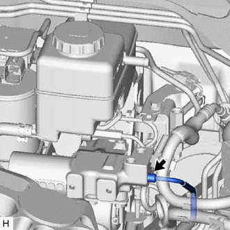
Using a union nut wrench, disconnect the brake tube flare nut.
-
-
REMOVE NO. 1 AIR DUCT SUB-ASSEMBLY
-
REMOVE NO. 1 HEATER TO REGISTER DUCT
-
REMOVE BRAKE PEDAL RETURN SPRING
-
REMOVE STOP LIGHT SWITCH ASSEMBLY
-
REMOVE PUSH ROD PIN
-
REMOVE BRAKE MASTER WITH STROKE SIMULATOR CYLINDER ASSEMBLY
-
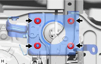
Remove the 4 nuts.
-
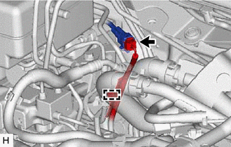
Disconnect the brake fluid level warning switch connector.
-
Detach the wire harness clamp.
Tech Tips
Disconnect the wire harness clamp after pulling out the brake master with simulator cylinder assembly a small amount.
-
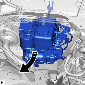
Remove the brake master with stroke simulator cylinder assembly.
Note
-
Do not kink or damage the No. 2 brake actuator tube.
-
Protect the surface of the relay block so that it does not become damaged on the brake master with stroke simulator cylinder assembly.
-
-
-
REMOVE BRAKE MASTER CYLINDER GASKET
-
Remove the brake master cylinder gasket from the brake master with stroke simulator cylinder assembly.
-