CAUTION / NOTICE / HINT
The necessary procedures (adjustment, calibration, initialization, or registration) that must be performed after parts are removed, installed, or replaced during skid control ECU assembly removal/installation are shown below.
| Replaced Part or Performed Procedure | Necessary Procedure | Effect/Inoperative Function when Necessary Procedure not Performed | Link |
|---|---|---|---|
| Auxiliary battery terminal is disconnected/reconnected | Memorize steering angle neutral point | LKA/LDA system (for Mono camera type) | for Stereo Camera type:Click here for Mono Camera type:Click here |
| Lane control system (for Stereo camera type) | |||
| Parking support brake system* | |||
| Pre-collision system (for Stereo camera type) | |||
| Pre-collision system (for Mono camera type) | |||
| Adaptive high beam system | |||
|
|||
| Variable gear ratio steering system | |||
| Parking assist monitor system | |||
| Panoramic view monitor system | |||
| Initialize rear door sunshade system | Rear door sunshade system | ||
| Initialize power trunk lid system | Power trunk lid system | ||
| Skid control ECU assembly |
|
|
for Initialization:Click here for Calibration:Click here |
CAUTION / NOTICE / HINT
While the auxiliary battery is connected, even if the power switch is off, the brake control system activates when the brake pedal is depressed or any door courtesy switch is turned on. Therefore, when servicing brake system components, do not depress the brake pedal or open/close the doors while the auxiliary battery is connected.
PROCEDURE
- Click here
PRECAUTION
Note:After turning the power switch off, waiting time may be required before disconnecting the cable from the negative (-) auxiliary battery terminal. Therefore, make sure to read the disconnecting the cable from the negative (-) auxiliary battery terminal notices before proceeding with work.
- Click here
INSTALL MAIN BODY ECU
- Click here
REMOVE SKID CONTROL ECU ASSEMBLY
-
Disconnect the 4 connectors from the skid control ECU assembly.
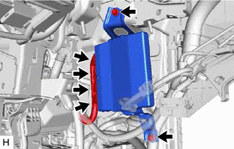
-
Remove the 2 bolts and skid control ECU assembly from the vehicle body.
-