| DTC Code | DTC Name |
|---|---|
| C1365 | Accumulator Pressure Sensor |
DESCRIPTION
The accumulator pressure sensor is built into the brake actuator assembly.
The skid control ECU assembly detects the accumulator pressure from the data sent from the accumulator pressure sensor, and then starts and stops the pump motor by operating the ABS motor relay.
This DTC may be stored if the accumulator pressure drops due to frequent braking (this is not a malfunction).
| DTC No. | Detection Item | INF Code | DTC Detection Condition | Trouble Area | Note |
|---|---|---|---|---|---|
| C1365 | Accumulator Pressure Sensor | 211 212 214 215 |
|
|
- |
CAUTION / NOTICE / HINT
When replacing the skid control ECU assembly or brake actuator assembly, perform initialization and calibration of the linear solenoid valve.
PROCEDURE
- Click here
CHECK HARNESS AND CONNECTOR (SKID CONTROL ECU ASSEMBLY - BRAKE ACTUATOR ASSEMBLY)
-
Make sure that there is no looseness at the locking part and the connecting part of the connectors.
-
Disconnect the A10 skid control ECU assembly connector.
-
Disconnect the A8 brake actuator assembly connector.
-
Measure the resistance according to the value(s) in the table below.
Standard Resistance Table 1. for LHD: Tester Connection Condition Specified Condition A10-8 (E) - A8-14 (E) Always Below 1 Ω A10-8 (E) or A8-14 (E) - Body ground Always 10 kΩ or higher A10-9 (VCM) - A8-10 (VCM) Always Below 1 Ω A10-9 (VCM) or A8-10 (VCM) - Body ground Always 10 kΩ or higher A10-21 (PAC1) - A8-15 (PAC1) Always Below 1 Ω A10-21 (PAC1) or A8-15 (PAC1) - Body ground Always 10 kΩ or higher A10-31 (PCK1) - A8-12 (PCK1) Always Below 1 Ω A10-31 (PCK1) or A8-12 (PCK1) - Body ground Always 10 kΩ or higher Table 2. for RHD: Tester Connection Condition Specified Condition A10-8 (E) - A8-45 (E) Always Below 1 Ω A10-8 (E) or A8-45 (E) - Body ground Always 10 kΩ or higher A10-9 (VCM) - A8-35 (VCM) Always Below 1 Ω A10-9 (VCM) or A8-35 (VCM) - Body ground Always 10 kΩ or higher A10-21 (PAC1) - A8-46 (PAC1) Always Below 1 Ω A10-21 (PAC1) or A8-46 (PAC1) - Body ground Always 10 kΩ or higher A10-31 (PCK1) - A8-37 (PCK1) Always Below 1 Ω A10-31 (PCK1) or A8-37 (PCK1) - Body ground Always 10 kΩ or higher Result Proceed to OK NG
- OKClick here
- NG
REPAIR OR REPLACE HARNESS OR CONNECTOR
-
- Click here
INSPECT SKID CONTROL ECU ASSEMBLY (SENSOR POWER SUPPLY OUTPUT)
-
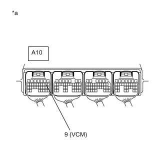
*a Component with harness connected
(Skid Control ECU Assembly)
Reconnect the A10 skid control ECU assembly connector.
-
Reconnect the A8 brake actuator assembly connector.
-
Turn the power switch on (IG).
-
Measure the voltage according to the value(s) in the table below.
Standard Voltage Tester Connection Condition Specified Condition A10-9 (VCM) - Body ground Power switch on (IG) 4.75 to 5.25 V Result Proceed to OK NG
- OKClick here
- NG
REPLACE SKID CONTROL ECU ASSEMBLY for LHD:Click here
REPLACE SKID CONTROL ECU ASSEMBLY for RHD:Click here
-
- Click here
INSPECT SKID CONTROL ECU ASSEMBLY (SENSOR INPUT)
-
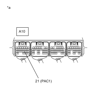
*a Component with harness connected
(Skid Control ECU Assembly)
Depress the brake pedal to operate the pump motor, and then check that the pump motor stops.
Note:Do not depress the brake pedal until the pump motor stops and the voltage check is finished in order to maintain the accumulator pressure.
-
Measure the voltage according to the value(s) in the table below.
Standard Voltage Tester Connection Condition Specified Condition A10-21 (PAC1) - Body ground Power switch on (IG), after pump motor operates and stops by pedal operation 3 to 4.7 V Result Proceed to OK NG
- OKClick here
- NG
REPLACE BRAKE ACTUATOR ASSEMBLY for LHD:Click here
REPLACE BRAKE ACTUATOR ASSEMBLY for RHD:Click here
-
- Click here
READ VALUE USING GTS (ACCUMULATOR PRESSURE SENSOR)
-
Turn the power switch off.
-
Connect the GTS to the DLC3.
-
Turn the power switch on (IG).
-
Select the Data List on the GTS.
- Chassis > ABS/VSC/TRC > Data List
Tester Display Measurement Item Range Normal Condition Diagnostic Note Accumulator Sensor Accumulator pressure sensor Min.: 0.00 V, Max.: 5.00 V Specified value: 2.60 to 3.80 V When brake fluid is stored in the accumulator: Accumulator pressure changes in accordance with volume of fluid stored in the accumulator -
-
- Chassis > ABS/VSC/TRC > Data List
Tester Display Accumulator Sensor -
-
-
-
- Chassis > ABS/VSC/TRC > Data List
-
Depress the brake pedal 4 or 5 times and operate the pump motor.
-
Wait for 30 seconds without depressing the brake pedal.
-
Check that the accumulator pressure sensor output value change is within the specified range.
OK Accumulator pressure sensor output value change is less than 0.20 V. Result Proceed to OK NG
- OKClick here
- NG
REPLACE BRAKE ACTUATOR ASSEMBLY for LHD:Click here
REPLACE BRAKE ACTUATOR ASSEMBLY for RHD:Click here
-
- Click here
RECONFIRM DTC
-
Clear the DTCs.
- Chassis > ABS/VSC/TRC > Clear DTCs
-
-
-
Turn the power switch off.
-
Turn the power switch on (READY).
-
Perform a road test.
-
Check if the same DTC is output.
- Chassis > ABS/VSC/TRC > Trouble Codes
-
-
Result Result Proceed to DTC C1365 is output. A DTC C1365 is not output. B
- A
REPLACE SKID CONTROL ECU ASSEMBLY for LHD:Click here
REPLACE SKID CONTROL ECU ASSEMBLY for RHD:Click here
- B
USE SIMULATION METHOD TO CHECKClick here
-