ELECTRONICALLY CONTROLLED BRAKE SYSTEM, Diagnostic DTC:C1256
| DTC Code | DTC Name |
|---|---|
| C1256 | Accumulator Low Pressure |
DESCRIPTION
The accumulator pressure sensor is built into the brake actuator assembly and detects the accumulator pressure.
The skid control ECU assembly turns on the brake warning light / yellow (minor malfunction), and sounds the meter buzzer if it senses a decrease in the accumulator pressure.
DTC C1256 may be stored if the accumulator pressure drops due to frequent braking (this is not a malfunction).
| DTC No. | Detection Item | INF Code | DTC Detection Condition | Trouble Area | Note |
|---|---|---|---|---|---|
| C1256 | Accumulator Low Pressure | 141 143 |
|
|
- |
| Vehicle Condition | ||||
|---|---|---|---|---|
| Pattern 1 | Pattern 2 | Pattern 3 | ||
| Diagnosis Condition | When vehicle speed is input | ○ | ○ | - |
| Malfunction Status | A brake pedal operation is input with the accumulator pressure low | ○ | - | - |
| A significant drop in accumulator pressure occurs while braking | - | ○ | - | |
| The accumulator low pressure condition (less than 14.62 MPa (149.1 kgf/cm2, 2121 psi)) continues from system startup |
- | - | ○ | |
| Detection Time | 0.3 seconds or more | 0.3 seconds or more | 120 seconds or more | |
| Number of Trips | 1 trip | 1 trip | 1 trip | |
| Vehicle Condition | |||||
|---|---|---|---|---|---|
| Pattern 1 | Pattern 2 | Pattern 3 | Pattern 4 | ||
| Diagnosis Condition | When vehicle speed is input | ○ | - | - | - |
| Malfunction Status | The accumulator pressure is low and any of the wheel cylinder pressure sensor values is lower than the target | ○ | - | - | - |
| The accumulator pressure is low and the wheel cylinder pressure for each wheel does not increase | - | ○ | - | - | |
| The ABS motor relay malfunction status continues and the accumulator pressure is less than 14.62 MPa (149.1 kgf/cm2, 2121 psi) |
- | - | ○ | - | |
| The ABS motor relay remains off and the accumulator pressure is less than 14.62 MPa (149.1 kgf/cm2, 2121 psi) |
- | - | - | ○ | |
| Detection Time | 0.5 seconds or more | - | 0.5 seconds or more | 0.5 seconds or more | |
| Number of Trips | 1 trip | 1 trip | 1 trip | 1 trip | |
CAUTION / NOTICE / HINT
Note
When replacing the brake actuator assembly, perform initialization and calibration of the linear solenoid valve.
PROCEDURE
-
CHECK DTC
-
Check if the same DTC is output.
Chassis > ABS/VSC/TRC > Trouble CodesResult Result Proceed to DTC C1256 is output. A DTCs C1202, C1241, C1252, C1253 and/or C1391 are output. B Tech Tips
-
External brake fluid leaks are suspected if C1202/68 is output.
-
An external brake fluid leak or an internal leak in the accumulator is suspected if C1391/69 is output.
-
B 
REPAIR CIRCUITS INDICATED BY OUTPUT DTCS Click here
A 
-
-
BRAKE PROBLEM CHECK
-
Ask the customer if frequent braking was performed while the brake warning light / yellow (minor malfunction) was on.
Result Result Proceed to Frequent braking was not performed. A Frequent braking was performed. B Tech Tips
This DTC may be stored even if the accumulator pressure drops only temporarily due to frequent braking.
B
END
A
-
-
INSPECT BRAKE BOOSTER WITH ACCUMULATOR PUMP ASSEMBLY
-
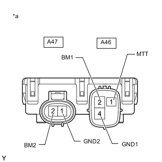
*a Component without harness connected
(Brake Booster with Accumulator Pump Assembly)
Make sure that there is no looseness at the locking part and the connecting part of the connectors.
-
Disconnect the A46 and A47 brake booster with accumulator pump assembly connectors.
-
Measure the resistance according to the value(s) in the table below.
Standard Resistance Tester Connection Condition Specified Condition A46-2 (BM1) - A46-4 (GND1) Always Below 10 Ω A47-2 (BM2) - A47-1 (GND2) Always Below 10 Ω A46-2 (BM1) - A47-2 (BM2) Always Below 1 Ω A46-4 (GND1) - A47-1 (GND2) Always Below 1 Ω A46-2 (BM1) - A46-1 (MTT) Always 950 to 1050 Ω A47-2 (BM2) - A46-1 (MTT) Always 950 to 1050 Ω Result Proceed to OK NG
NG
REPLACE BRAKE BOOSTER WITH ACCUMULATOR PUMP ASSEMBLY Click here
OK
-
-
READ VALUE USING GTS (ACCUMULATOR PRESSURE SENSOR)
-
Reconnect the A46 and A47 brake booster with accumulator pump assembly connectors.
-
Connect the GTS to the DLC3.
-
Turn the power switch on (IG).
-
Select the Data List on the GTS.
Chassis > ABS/VSC/TRC > Data ListTester Display Measurement Item Range Normal Condition Diagnostic Note Accumulator Sensor Accumulator pressure sensor Min.: 0.00 V, Max.: 5.00 V Specified value: 2.60 to 3.80 V When brake fluid is stored in the accumulator: Accumulator pressure changes in accordance with volume of fluid stored in the accumulator
Chassis > ABS/VSC/TRC > Data ListTester Display Accumulator Sensor -
Depress the brake pedal 4 or 5 times and operate the pump motor.
-
Wait for 30 seconds without depressing the brake pedal.
-
Check that the accumulator pressure sensor output value change is within the specified range.
OK Accumulator pressure sensor output value change is less than 0.20 V. Tech Tips
-
This inspection is performed to determine if a long-term power malfunction occurred when low pressure is detected due to a defective sensor, an internal leak in the brake actuator assembly, or deterioration of the accumulator.
-
External brake fluid leaks are suspected if the fluid level drops inside the brake master cylinder reservoir assembly.
Result Proceed to OK NG -
OK
USE SIMULATION METHOD TO CHECK Click here
NG
-
-
PERFORM ACTIVE TEST USING GTS (SOLENOID VALVE)
-
Select the Active Test on the GTS.
Chassis > ABS/VSC/TRC > Active TestTester Display Measurement Item Control Range Diagnostic Note ECB Solenoid (SMC1) Master cut solenoid (SMC1) Solenoid ON/OFF ECB: Electronically Controlled Brake System ECB: Electronically Controlled Brake System
Tech Tips
The Active Test can be performed when the following conditions are met.
-
ABS main relay is on.
-
Shift state is park (P).
-
Parking brake is applied.
-
Vehicle speed is 0 km/h (0 mph).
-
-
Perform the Active Test of the solenoid using the GTS.
-
Select the Data List on the GTS.
Chassis > ABS/VSC/TRC > Data ListTester Display Measurement Item Range Normal Condition Diagnostic Note FR W/C Sensor Front wheel cylinder pressure sensor RH Min.: 0.00 V, Max.: 5.00 V Brake pedal released: 0.30 to 0.70 V Reading increases when brake pedal is depressed
Chassis > ABS/VSC/TRC > Active TestActive Test Display ECB Solenoid (SMC1) Data List Display FR W/C Sensor -
Check that the output value of the wheel cylinder pressure sensor does not increase.
OK The output value of the wheel cylinder pressure sensor does not increase. Tech Tips
If output value increases, there may be brake fluid leaks in the brake actuator assembly.
Result Result Proceed to The output values of the wheel cylinder pressure sensors do not increase. A The output value of the wheel cylinder pressure sensor increases. B
B
REPLACE BRAKE ACTUATOR ASSEMBLY for LHD: Click here
REPLACE BRAKE ACTUATOR ASSEMBLY for RHD: Click hereA
-
-
PERFORM ACTIVE TEST USING GTS (SOLENOID VALVE)
-
Select the Active Test on the GTS.
Chassis > ABS/VSC/TRC > Active TestTester Display Measurement Item Control Range Diagnostic Note ECB Solenoid (SMC2) Master cut solenoid (SMC2) Solenoid ON/OFF ECB: Electronically Controlled Brake System ECB: Electronically Controlled Brake System
Tech Tips
The Active Test can be performed when the following conditions are met.
-
ABS main relay is on.
-
Shift state is park (P).
-
Parking brake is applied.
-
Vehicle speed is 0 km/h (0 mph).
-
-
Perform the Active Test of the solenoid using the GTS.
-
Select the Data List on the GTS.
Chassis > ABS/VSC/TRC > Data ListTester Display Measurement Item Range Normal Condition Diagnostic Note FL W/C Sensor Front wheel cylinder pressure sensor LH Min.: 0.00 V, Max.: 5.00 V Brake pedal released: 0.30 to 0.70 V Reading increases when brake pedal is depressed
Chassis > ABS/VSC/TRC > Active TestActive Test Display ECB Solenoid (SMC2) Data List Display FL W/C Sensor -
Check that the output value of the wheel cylinder pressure sensor does not increase.
OK The output value of the wheel cylinder pressure sensor does not increase. Tech Tips
If output value increases, there may be brake fluid leaks in the brake actuator assembly.
Result Result Proceed to The output values of the wheel cylinder pressure sensors do not increase. A The output value of the wheel cylinder pressure sensor increases. B
B
REPLACE BRAKE ACTUATOR ASSEMBLY for LHD: Click here
REPLACE BRAKE ACTUATOR ASSEMBLY for RHD: Click hereA
-
-
PERFORM ACTIVE TEST USING GTS (SOLENOID VALVE)
-
Select the Active Test on the GTS.
Chassis > ABS/VSC/TRC > Active TestTester Display Measurement Item Control Range Diagnostic Note ECB Solenoid (SLRRR) Linear solenoid (RRR) valve Valve close ON/OFF ECB: Electronically Controlled Brake System ECB: Electronically Controlled Brake System
Tech Tips
The Active Test can be performed when the following conditions are met.
-
ABS main relay is on.
-
Shift state is park (P).
-
Parking brake is applied.
-
Vehicle speed is 0 km/h (0 mph).
-
-
Perform the Active Test of the solenoid using the GTS.
-
Select the Data List on the GTS.
Chassis > ABS/VSC/TRC > Data ListTester Display Measurement Item Range Normal Condition Diagnostic Note RR W/C Sensor Rear wheel cylinder pressure sensor RH Min.: 0.00 V, Max.: 5.00 V Brake pedal released: 0.30 to 0.70 V Reading increases when brake pedal is depressed
Chassis > ABS/VSC/TRC > Active TestActive Test Display ECB Solenoid (SLRRR) Data List Display RR W/C Sensor -
Check that the output value of the wheel cylinder pressure sensor does not increase.
OK The output value of the wheel cylinder pressure sensor does not increase. Tech Tips
If output value increases, there may be brake fluid leaks in the brake actuator assembly.
Result Result Proceed to The output values of the wheel cylinder pressure sensors do not increase. A The output value of the wheel cylinder pressure sensor increases. B
B
REPLACE BRAKE ACTUATOR ASSEMBLY for LHD: Click here
REPLACE BRAKE ACTUATOR ASSEMBLY for RHD: Click hereA
-
-
PERFORM ACTIVE TEST USING GTS (SOLENOID VALVE)
-
Select the Active Test on the GTS.
Chassis > ABS/VSC/TRC > Active TestTester Display Measurement Item Control Range Diagnostic Note ECB Solenoid (SLRRL) Linear solenoid (RLR) valve Valve close ON/OFF ECB: Electronically Controlled Brake System ECB: Electronically Controlled Brake System
Tech Tips
The Active Test can be performed when the following conditions are met.
-
ABS main relay is on.
-
Shift state is park (P).
-
Parking brake is applied.
-
Vehicle speed is 0 km/h (0 mph).
-
-
Perform the Active Test of the solenoid using the GTS.
-
Select the Data List on the GTS.
Chassis > ABS/VSC/TRC > Data ListTester Display Measurement Item Range Normal Condition Diagnostic Note RL W/C Sensor Rear wheel cylinder pressure sensor LH Min.: 0.00 V, Max.: 5.00 V Brake pedal released: 0.30 to 0.70 V Reading increases when brake pedal is depressed
Chassis > ABS/VSC/TRC > Active TestActive Test Display ECB Solenoid (SLRRL) Data List Display RL W/C Sensor -
Check that the output value of the wheel cylinder pressure sensor does not increase.
OK The output value of the wheel cylinder pressure sensor does not increase. Tech Tips
If output value increases, there may be brake fluid leaks in the brake actuator assembly.
Result Result Proceed to The output values of the wheel cylinder pressure sensors do not increase. A The output value of the wheel cylinder pressure sensor increases. B
A
REPLACE BRAKE BOOSTER WITH ACCUMULATOR PUMP ASSEMBLY Click here
B
REPLACE BRAKE ACTUATOR ASSEMBLY for LHD: Click here
REPLACE BRAKE ACTUATOR ASSEMBLY for RHD: Click here -