FRONT LOWER SUSPENSION ARM(for AWD) REMOVAL

CAUTION / NOTICE / HINT
The necessary procedures (adjustment, calibration, initialization, or registration) that must be performed after parts are removed, installed, or replaced during the front lower suspension arm removal/installation are shown below.
| Necessary Procedure After Parts Removed/Installed/Replaced | ||||||||||||||||||
|---|---|---|---|---|---|---|---|---|---|---|---|---|---|---|---|---|---|---|
|
Note
-
When the brake pedal is first depressed after replacing the brake pads or pushing back the disc brake piston, DTC C1341, C1342, C1343 and/or C1344 may be stored. As there is no malfunction, clear the DTCs.
-
While the auxiliary battery is connected, even if the power switch is off, the brake control system activates when the brake pedal is depressed or any door courtesy switch is turned on. Therefore, when servicing, do not depress the brake pedal or open/close the doors while the auxiliary battery is connected.
-
Be sure to read the "PRECAUTION" thoroughly before servicing.
Tech Tips
-
Use the same procedure for the RH and LH side.
-
The following procedure is for the LH side.
PROCEDURE
-
AIR SUSPENSION CONTROL PROHIBITED (w/ Air Suspension)
-
REMOVE NO.1 ENGINE UNDER COVER ASSEMBLY
-
REMOVE NO.2 ENGINE UNDER COVER ASSEMBLY
-
REMOVE FRONT SUSPENSION MEMBER BRACE
-
REMOVE STRUT BAR BRACKET SUPPORT SUB-ASSEMBLY
-
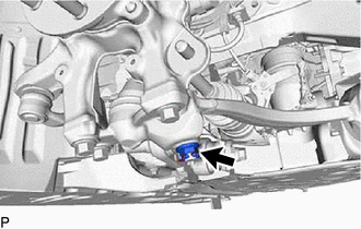
DISCONNECT BRAKE BOOSTER PUMP CONNECTOR
-
for LHD:
-
for RHD:
-
-
REMOVE FRONT WHEEL
-
REMOVE FRONT AXLE SHAFT NUT LH
-
DISCONNECT DISC BRAKE CYLINDER ASSEMBLY LH
-
REMOVE FRONT DISC LH
-
REMOVE FRONT DISC BRAKE DUST COVER LH
-
DISCONNECT FRONT HEIGHT CONTROL SENSOR SUB-ASSEMBLY LH
-
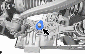
DISCONNECT LOWER NO. 2 SUSPENSION ARM ASSEMBLY LH
-
Remove the clip and nut.
-
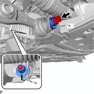
Install SST (attachment) onto the lower No. 2 suspension arm assembly LH so that there is a space of approximately 2 mm (0.0787 in.) between the arm and attachment.
- SST
- 09628-50010 ( 09628-05010 )
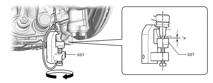
*a 2 mm (0.0787 in.) - - Note
-
Be sure to install SST (attachment) in order to prevent damage to the lower No. 2 suspension arm assembly LH stud.
-
As SST may become damaged, make sure the space between the arm and spacers is not 2 mm (0.0787 in.) or less.
-
Using SST, disconnect the lower No. 2 suspension arm assembly LH from the front lower ball joint assembly LH.
- SST
- 09628-50010 ( 09628-05010 )
Note
-
Apply molybdenum grease to the bolt threads and end of the SST bolt.
-
Do not damage the dust cover of the lower No. 2 suspension arm assembly LH.
-
Make sure that the bolt of SST and thelower No. 2 suspension arm assembly LH ball are in a straight line when installing SST.
-
Be sure to tie the string of SST to the vehicle to prevent SST from dropping.
-
Do not apply a torque of 160 N*m (1631 kgf*cm, 118 ft.*lbf) or more to SST as it may be damaged.
-
-
REMOVE LOWER NO. 2 SUSPENSION ARM ASSEMBLY LH
-
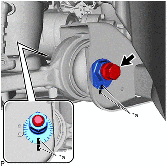
*a Matchmark Put matchmarks on the front suspension toe adjust cam sub-assembly and front frame assembly.
-
Put matchmarks on the front No.2 suspension toe adjust plate and front frame assembly.
-
Remove the front No.2 suspension toe adjust plate and bolt.
-
Remove the front suspension toe adjust cam sub-assembly and the lower No. 2 suspension arm assembly LH.
-
-
DISCONNECT FRONT SPEED SENSOR LH
-
DISCONNECT TIE ROD ASSEMBLY LH
-
DISCONNECT STEERING KNUCKLE LH
-
REMOVE STEERING KNUCKLE LH
-
REMOVE FRONT LOWER BALL JOINT ASSEMBLY LH
-
REMOVE FRONT STABILIZER LINK ASSEMBLY LH
-
DISCONNECT FRONT LOWER SHOCK ABSORBER BRACKET SUB-ASSEMBLY LH
-
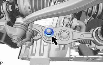
Remove the nut.
-
Remove the front upper shock absorber bracket plate and disconnect the front lower shock absorber bracket sub-assembly LH from the front lower suspension arm assembly LH.
-
-
REMOVE FRONT LOWER SUSPENSION ARM ASSEMBLY LH
-
*a Matchmark Put matchmarks on the front suspension toe adjust cam sub-assembly and front frame assembly.
-
Put matchmarks on the front No.2 suspension toe adjust plate and front frame assembly.
-
Remove the front No.2 suspension toe adjust plate and bolt.
-
Remove the front suspension toe adjust cam sub-assembly and the front lower suspension arm assembly LH.
-