CAUTION / NOTICE / HINT
The necessary procedures (adjustment, calibration, initialization, or registration) that must be performed after parts are removed, installed, or replaced during the front lower suspension arm removal/installation are shown below.
| Necessary Procedure After Parts Removed/Installed/Replaced | ||||||||||||||||||||||
|---|---|---|---|---|---|---|---|---|---|---|---|---|---|---|---|---|---|---|---|---|---|---|
|
-
When the brake pedal is first depressed after replacing the brake pads or pushing back the disc brake piston, DTC C1341, C1342, C1343 and/or C1344 may be stored. As there is no malfunction, clear the DTCs.
-
While the auxiliary battery is connected, even if the power switch is off, the brake control system activates when the brake pedal is depressed or any door courtesy switch is turned on. Therefore, when servicing, do not depress the brake pedal or open/close the doors while the auxiliary battery is connected.
-
Be sure to read the "PRECAUTION" thoroughly before servicing.
-
Use the same procedure for the RH and LH side.
-
The following procedure is for the LH side.
PROCEDURE
- Click here
AIR SUSPENSION CONTROL PROHIBITED (w/ Air Suspension)
- Click here
DISCONNECT BRAKE BOOSTER PUMP CONNECTOR
-
for LHD:
-
for RHD:
-
- Click here
REMOVE FRONT WHEEL
- Click here
REMOVE FRONT LOWER SUSPENSION ARM ASSEMBLY LH
-
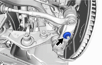
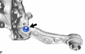
Remove the clip and nut.
-
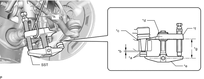
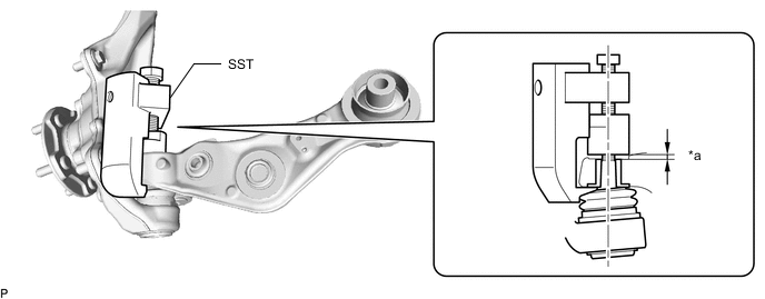
*a SST (Spacer A) *b 1 mm (0.0394 in.) *c Spacer *d Center Nut *e Body *f Claw *g Parallel *h String Install 2 SST (spacer A) onto the front lower suspension arm assembly LH so that there is a space of approximately 1 mm (0.0394 in.) between the arm and spacers.
09960-20010 09961-02050 Note:
-
Make sure to install the spacers (SST spacer A) as the steering knuckle spacer may shift.
-
As SST may become damaged, make sure the space between the arm and spacers is not 1 mm (0.0394 in.) or less.
-
-
Using SST, disconnect the front lower suspension arm assembly LH from the steering knuckle assembly LH.
09960-20010 09961-02010 Note:
-
Apply molybdenum grease to the bolt threads and end of the SST bolt.
-
Do not damage the dust cover.
-
As the dust cover may be damaged, adjust SST with the center nut so that the body and claw are parallel.
-
Make sure to tie the string of SST to the vehicle to prevent SST from dropping.
-
-

Bolt 
Nut Remove the bolt, nut and front lower suspension arm assembly LH.
-
- Click here
DISCONNECT DISC BRAKE CYLINDER ASSEMBLY LH
- Click here
REMOVE FRONT DISC LH
-
for 6-Pot Caliper:
-
except 6-Pot Caliper:
-
- Click here
REMOVE TRANSMISSION UNDER COVER
- Click here
REMOVE NO. 2 ENGINE UNDER COVER ASSEMBLY
-
Bolt Screw Remove the 10 bolts, 4 screws, clip and No. 2 engine under cover assembly.
-
- Click here
REMOVE ENGINE SIDE COVER LH
-
Disconnect the clamp and 4 clips and remove the engine side cover LH.
-
- Click here
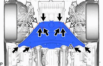
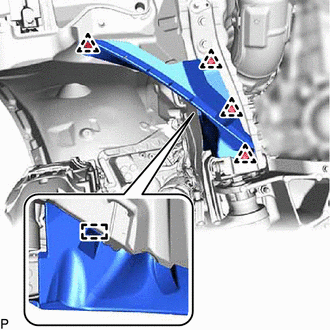
REMOVE REAR LOWER ARM MOUNTING REINFORCEMENT SUB-ASSEMBLY LH
-
Remove the 4 bolts and rear lower arm mounting reinforcement sub-assembly LH.
-
- Click here
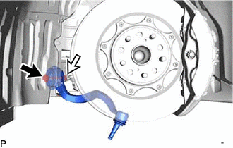
DISCONNECT FRONT HEIGHT CONTROL SENSOR SUB-ASSEMBLY LH
- Click here
DISCONNECT FRONT STABILIZER LINK ASSEMBLY LH
- Click here
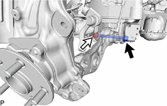
DISCONNECT FRONT SHOCK ABSORBER ASSEMBLY LH (w/o Air Suspension)
-
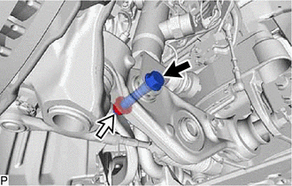
Bolt Nut Remove the bolt and nut, and separate the front shock absorber assembly LH from the lower No. 2 suspension arm assembly LH.
Note:Because the nut has its own stopper, do not turn the nut. Loosen the bolt with the nut secured.
-
- Click here
DISCONNECT FRONT PNEUMATIC CYLINDER WITH SHOCK ABSORBER ASSEMBLY LH (w/ Air Suspension)
Tip:Perform the same procedure as for the front shock absorber assembly LH.
- Click here
DISCONNECT TIE ROD ASSEMBLY LH
- Click here
DISCONNECT STEERING KNUCKLE ASSEMBLY LH
- Click here
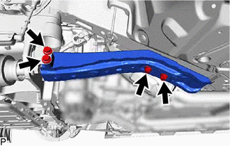
REMOVE LOWER NO. 2 SUSPENSION ARM ASSEMBLY LH
-
Bolt Nut Remove the bolt, nut and lower No. 2 suspension arm assembly LH.
-
Remove the clip and nut.
-
*a 2 mm (0.0787 in.) - - Install SST (attachment) onto the lower No. 2 suspension arm assembly LH so that there is a space of approximately 2 mm (0.0787 in.) between the arm and attachment.
09628-50010 09628-05010 Note:
-
Make sure to install the attachment (SST attachment) as the lower No. 2 suspension arm assembly LH spacer may shift.
-
As SST may become damaged, make sure the space between the arm and spacers is not 2 mm (0.0787 in.) or less.
-
-
Using SST, disconnect the lower No. 2 suspension arm assembly LH from the steering knuckle assembly LH.
09628-50010 09628-05010 Note:
-
Apply molybdenum grease to the bolt threads and end of the SST bolt.
-
Do not damage the dust cover.
-
As the dust cover may be damaged, adjust SST with the center nut so that the body and crow are parallel.
-
Do not apply a torque of 160 N*m (1631 kgf*cm, 118 ft.*lbf) or more to SST as it may be damaged.
-
-