FRONT PNEUMATIC CYLINDER(for AWD) REMOVAL
CAUTION / NOTICE / HINT
The necessary procedures (adjustment, calibration, initialization, or registration) that must be performed after parts are removed, installed, or replaced during the front pneumatic cylinder removal/installation are shown below.
| Necessary Procedure After Parts Removed/Installed/Replaced | ||||||||||||||
|---|---|---|---|---|---|---|---|---|---|---|---|---|---|---|
|
Note
-
Be sure to read the "PRECAUTION" thoroughly before servicing.
-
In order to prevent the battery from becoming fully depleted, connect the battery charger to the auxiliary battery when turning the power switch on (IG) to charge the battery.
-
Keep the power supply connected to prevent the GTS battery from becoming fully depleted.
Tech Tips
-
Use the same procedure for the RH and LH side.
-
The following procedure is for the LH side.
PROCEDURE
-
AIR SUSPENSION CONTROL PROHIBITED (WHEN REPLACING A FRONT PNEUMATIC CYLINDER)
-
AIR SUSPENSION CONTROL PROHIBITED (WHEN REPLACING THE 2 FRONT PNEUMATIC CYLINDERS)
-
REMOVE UPPER RADIATOR SUPPORT SEAL (for LH Side)
-
REMOVE RADIATOR COVER PLATE (for RH Side)
-
REMOVE STEERING KNUCKLE LH
-
REMOVE FRONT FLEXIBLE HOSE BRACKET LH
-
DISCONNECT FRONT HEIGHT CONTROL SENSOR SUB-ASSEMBLY LH
-
REMOVE FRONT STABILIZER LINK ASSEMBLY LH
-
DISCONNECT NO.4 HEIGHT CONTROL TUBE
-
REMOVE FRONT SHOCK ABSORBER CAP LH
-
REMOVE FRONT PNEUMATIC CYLINDER WITH SHOCK ABSORBER ASSEMBLY LH
-
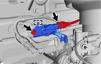
Disconnect the connector.
-
Remove the bolt.
-
Disengage the guide to disconnect the absorber control wire.
-
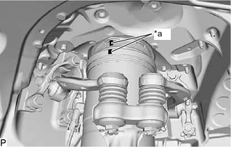
*a Matchmark When reusing the front pneumatic cylinder with shock absorber assembly LH:
-
Place matchmarks on the front suspension support assembly and pneumatic cylinder chamber.
-
-
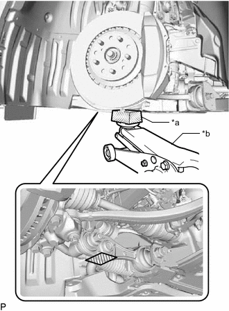
*a Wooden Block *b Jack Support the front lower suspension arm assembly LH using a jack and wooden block.
-
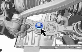
Remove the nut.
-
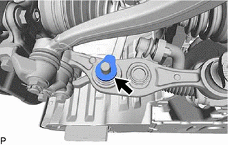
Remove the front upper shock absorber bracket plate, and disconnect the front lower shock absorber bracket sub-assembly LH from the front lower suspension arm assembly LH.
-
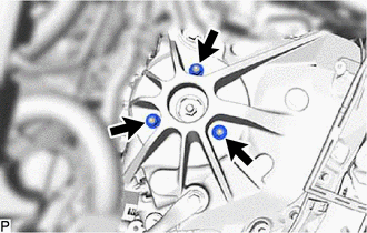
Remove the 3 nuts from the front pneumatic cylinder with shock absorber assembly LH (upper side).
-
Slowly lower the jack and remove the front pneumatic cylinder with shock absorber assembly LH.
-
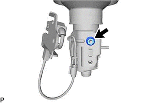
Remove the nut.
-
When reusing the front pneumatic cylinder with shock absorber assembly LH:
-
Remove the No. 2 connector, plate and 2 O-rings.
-
-
-
REMOVE FRONT LOWER SHOCK ABSORBER BRACKET SUB-ASSEMBLY LH