CAUTION / NOTICE / HINT
The necessary procedures (adjustment, calibration, initialization, or registration) that must be performed after parts are removed, installed, or replaced during the front shock absorber removal/installation are shown below.
| Necessary Procedure After Parts Removed/Installed/Replaced | ||||||||||||||||||
|---|---|---|---|---|---|---|---|---|---|---|---|---|---|---|---|---|---|---|
|
-
When the brake pedal is first depressed after replacing the brake pads or pushing back the disc brake piston, DTC C1341, C1342, C1343 and/or C1344 may be stored. As there is no malfunction, clear the DTCs.
-
While the auxiliary battery is connected, even if the power switch is off, the brake control system activates when the brake pedal is depressed or any door courtesy switch is turned on. Therefore, when servicing, do not depress the brake pedal or open/close the doors while the auxiliary battery is connected.
-
Use the same procedure for the RH and LH side.
-
The following procedure is for the LH side.
PROCEDURE
- Click here
DISCONNECT BRAKE BOOSTER PUMP CONNECTOR
-
for LHD:
-
for RHD:
-
- Click here
REMOVE UPPER RADIATOR SUPPORT SEAL (for LH Side)
- Click here
REMOVE RADIATOR COVER PLATE (for RH Side)
- Click here
REMOVE FRONT WHEEL
- Click here
REMOVE ABSORBER CONTROL WIRE LH
-
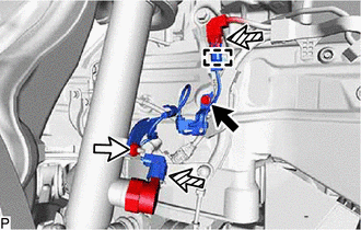

Bolt 
Nut 
Connector Remove the bolt and nut.
-
Disconnect the clamp, 2 connectors and remove the absorber control wire LH.
-
- Click here
DISCONNECT FRONT STABILIZER LINK ASSEMBLY LH
-
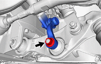
Remove the nut and disconnect the front stabilizer link assembly LH.
Tip:If the ball joint turns together with the nut, use a hexagon socket wrench 8 mm to hold the stud bolt.
-
- Click here
DISCONNECT FRONT HEIGHT CONTROL SENSOR SUB-ASSEMBLY LH
-
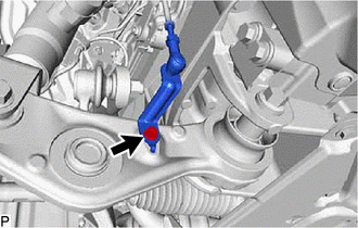
Remove the bolt and disconnect the front height control sensor sub-assembly LH.
-
- Click here
DISCONNECT FRONT SKID CONTROL SENSOR WIRE LH
-
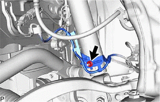
Remove the nut and disconnect the front skid control sensor wire LH.
-
- Click here
DISCONNECT DISC BRAKE CYLINDER ASSEMBLY LH
- Click here
DISCONNECT STEERING KNUCKLE ASSEMBLY LH
- Click here
REMOVE FRONT SHOCK ABSORBER CAP LH
-
Remove the front shock absorber cap LH.
-
- Click here
REMOVE FRONT SHOCK ABSORBER WITH COIL SPRING
-
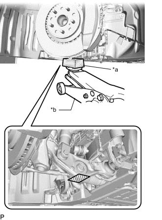
*a Wooden Block *b Jack Support the lower No. 2 suspension arm assembly LH using a jack and wooden block.
-
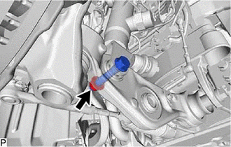
Remove the nut.
Note:
-
Because the nut has its own stopper, do not turn the nut. Loosen the bolt with the nut secured.
-
Do not remove the bolt.
-
-
Loosen the lock nut.
CAUTION: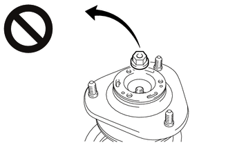
-
Only loosen the lock nut, do not remove it.
-
If the lock nut is removed with the front coil spring under tension, components of the front shock absorber LH with coil spring may fly off.
Note:If the front shock absorber LH with coil spring will not be disassembled, do not loosen the lock nut.
-
-
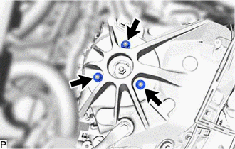
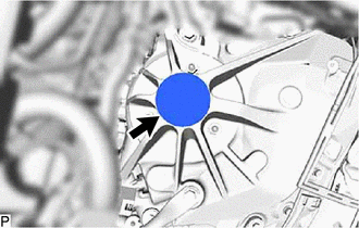
Remove the 3 nuts from the front shock absorber with coil spring (upper side).
-
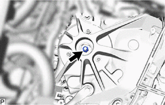
Remove the bolt from the front shock absorber with coil spring (lower side).
-
Slowly lower the jack and remove the front shock absorber with coil spring.
-
- Click here
REMOVE FRONT SHOCK ABSORBER ASSEMBLY LH
-
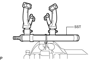
Secure SST in a vise.
09727-30022 09727-00010 09727-00022 09727-00031 -
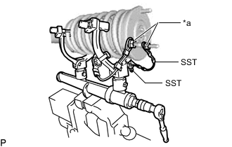
Attach the hooks of each SST arm across the diameter of the coil spring.
CAUTION:
-
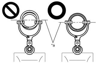
*a Front Coil Spring Diameter Do not perform the work without checking to make sure that the claws of the hooks are securely engaged.
-
It could cause the hook to slip off and the spring to fly out, which could result in an injury.
-
Do not install SST to the front coil spring unless its top and bottom hook distance is set to the widest condition.
-
It could cause the hook to slip off and the spring to fly out, which could result in an injury.
-
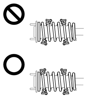
Do not install SST when the distances between the SST arms or the number of coils of the coil spring between the hooks are not the same.
-
It could cause the hook to slip off and the spring to fly out, which could result in an injury.
-
-
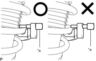
*a Stopper Pin Install the stopper pins to the hooks of SST.
CAUTION:Do not perform the work if the stopper pin is not securely installed.
-
*a Vehicle Nut Install SST and 2 vehicle nuts to the upper support as shown in the illustration.
09727-30022 09727-00090 09727-00100 -
Using SST, compress the coil spring.
CAUTION:
-
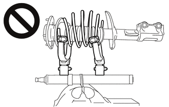
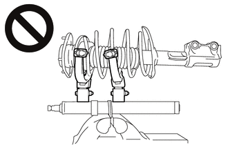
While compressing the spring, if the front coil spring starts to bend into a bow shape, do not continue the work.
-
It could cause the hook to slip off and the spring to fly out, which could result in an injury.
-
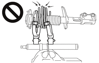
Do not compress the springs so far that the coils of the springs touch each other.
-
It could cause the hook to slip off and the spring to fly out, which could result in an injury.
-
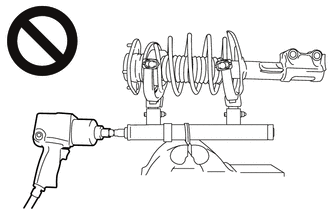
Do not use an impact wrench.
-
The threads may be stripped, or the sudden compression may result in slack that causes the hooks to slip off, causing the spring to fly out and possibly resulting in injury.
-
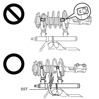
If a stopper pin touches the coil spring while using SST, remove the stopper pin and continue with the procedure.
-
If a stopper pin is removed, install a coil spring stopper belt as shown in the illustration.
09727-00110 -
-
Check that the front coil spring has become free, and remove the front support to front shock absorber lock nut.
CAUTION: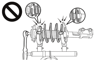
-
If the front coil spring has not become free, do not remove the front support to front shock absorber lock nut.
-
The spring force will cause the components to be scattered, possibly resulting in injury.
-
-
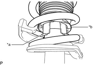
*a Front Shock Absorber Assembly LH Claw *b End of Front Upper Coil Spring Insulator Remove the front suspension support assembly from the front shock absorber assembly LH.
Note:Turn the front suspension support assembly to disengage the end of the front upper coil spring insulator from the front shock absorber assembly LH claws.
-
Remove the front upper coil spring insulator from the front suspension support assembly.
-
Remove the front spring bumper from the front suspension support assembly.
-
Remove the front coil spring and SST.
Note:Do not use an impact wrench. It will damage SST.
-
Remove the front lower coil spring insulator from the front shock absorber assembly LH.
-