CAUTION / NOTICE / HINT
The necessary procedures (adjustment, calibration, initialization, or registration) that must be performed after parts are removed, installed, or replaced during the front upper suspension arm removal/installation are shown below.
| Necessary Procedure After Parts Removed/Installed/Replaced | ||||||||||||||||||
|---|---|---|---|---|---|---|---|---|---|---|---|---|---|---|---|---|---|---|
|
-
Use the same procedure for the RH and LH side.
-
The following procedure is for the LH side.
PROCEDURE
- Click here
AIR SUSPENSION CONTROL PROHIBITED (w/ Air Suspension)
- Click here
REMOVE FRONT WHEEL
- Click here
DISCONNECT STEERING KNUCKLE ASSEMBLY LH (for 2WD)
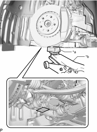
-
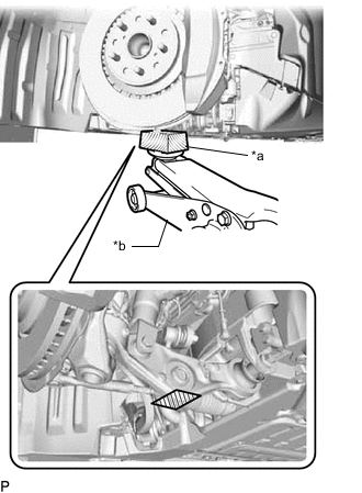
*a Wooden Block *b Jack Support the lower No. 2 suspension arm assembly LH using a jack and wooden block.
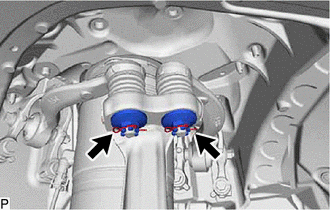
-
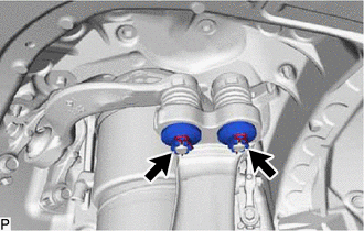
Remove the 2 clips and 2 nuts.
-
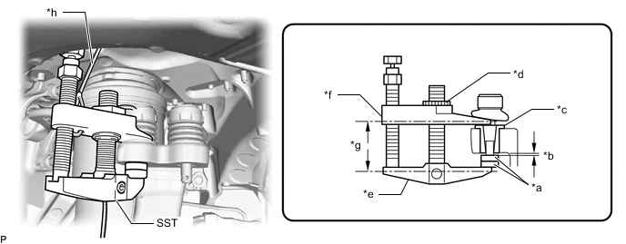
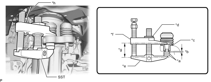
*a SST (Spacer B) *b 1 mm (0.0394 in.) *c Spacer *d Center Nut *e Body *f Claw *g Parallel *h String Install 2 SST (spacer B) onto the front upper No. 1 suspension arm assembly LH so that there is a space of approximately 1 mm (0.0394 in.) between the arm and spacers.
09960-20010 09961-02060 Note:
-
Make sure to install the spacers (SST spacer B) as the steering knuckle spacer may shift.
-
As SST may become damaged, make sure the space between the arm and spacers is not 1 mm (0.0394 in.) or less.
-
-
Using SST, disconnect the steering knuckle assembly LH from the front upper No. 1 suspension arm assembly LH.
09960-20010 09961-02010 Note:
-
Apply molybdenum grease to the bolt threads and end of the SST bolt.
-
Do not damage the dust cover.
-
As the dust cover may be damaged, adjust SST with the center nut so that the body and claw are parallel.
-
Make sure to tie the string of SST to the vehicle to prevent SST from dropping.
-
-
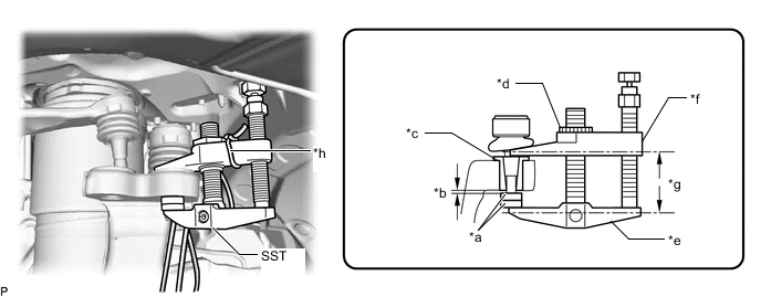
*a SST (Spacer B) *b 1 mm (0.0394 in.) *c Spacer *d Center Nut *e Body *f Claw *g Parallel *h String Install 2 SST (spacer B) onto the front upper No. 2 suspension arm assembly LH so that there is a space of approximately 1 mm (0.0394 in.) between the arm and spacers.
09960-20010 09961-02060 Note:
-
Make sure to install the spacers (SST spacer B) as the steering knuckle spacer may shift.
-
As SST may become damaged, make sure the space between the arm and spacers is not 1 mm (0.0394 in.) or less.
-
-
Using SST, disconnect the steering knuckle assembly LH from the front upper No. 2 suspension arm assembly LH.
09960-20010 09961-02010 Note:
-
Apply molybdenum grease to the bolt threads and end of the SST bolt.
-
Do not damage the dust cover.
-
As the dust cover may be damaged, adjust SST with the center nut so that the body and claw are parallel.
-
Make sure to tie the string of SST to the vehicle to prevent SST from dropping.
-
-
- Click here
DISCONNECT STEERING KNUCKLE ASSEMBLY LH (for AWD)
-
*a Wooden Block *b Jack Support the front suspension lower arm assembly LH using a jack and wooden block.
-
Remove the 2 clips and 2 nuts.
-
*a SST (Spacer B) *b 1 mm (0.0394 in.) *c Spacer *d Center Nut *e Body *f Claw *g Parallel *h String Install 2 SST (spacer B) onto the front upper No. 1 suspension arm assembly LH so that there is a space of approximately 1 mm (0.0394 in.) between the arm and spacers.
09960-20010 09961-02060 Note:
-
Make sure to install the spacers (SST spacer B) as the steering knuckle spacer may shift.
-
As SST may become damaged, make sure the space between the arm and spacers is not 1 mm (0.0394 in.) or less.
-
-
Using SST, disconnect the steering knuckle assembly LH from the front upper No. 1 suspension arm assembly LH.
09960-20010 09961-02010 Note:
-
Apply molybdenum grease to the bolt threads and end of the SST bolt.
-
Do not damage the dust cover.
-
As the dust cover may be damaged, adjust SST with the center nut so that the body and claw are parallel.
-
Make sure to tie the string of SST to the vehicle to prevent SST from dropping.
-
-
*a SST (Spacer B) *b 1 mm (0.0394 in.) *c Spacer *d Center Nut *e Body *f Claw *g Parallel *h String Install 2 SST (spacer B) onto the front upper No. 2 suspension arm assembly LH so that there is a space of approximately 1 mm (0.0394 in.) between the arm and spacers.
09960-20010 09961-02060 Note:
-
Make sure to install the spacers (SST spacer B) as the steering knuckle spacer may shift.
-
As SST may become damaged, make sure the space between the arm and spacers is not 1 mm (0.0394 in.) or less.
-
-
Using SST, disconnect the steering knuckle assembly LH from the front upper No. 2 suspension arm assembly LH.
09960-20010 09961-02010 Note:
-
Apply molybdenum grease to the bolt threads and end of the SST bolt.
-
Do not damage the dust cover.
-
As the dust cover may be damaged, adjust SST with the center nut so that the body and claw are parallel.
-
Make sure to tie the string of SST to the vehicle to prevent SST from dropping.
-
-
- Click here
REMOVE FRONT UPPER NO. 1 ARM BRACKET LH (for 2WD)
-
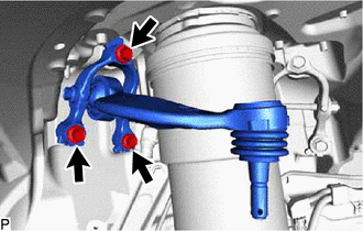
Remove the 3 bolts, front upper No. 1 arm bracket LH and front upper No. 1 suspension arm assembly LH.
-
- Click here
REMOVE FRONT UPPER NO. 2 ARM BRACKET LH (for 2WD)
-
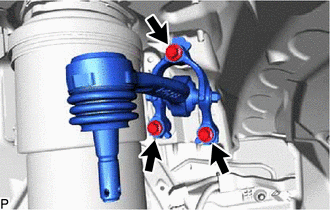
Remove the 3 bolts, front upper No. 2 arm bracket LH and front upper No. 2 suspension arm assembly LH.
-
- Click here
REMOVE FRONT UPPER NO. 1 ARM BRACKET LH (for AWD)
-
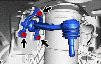
Remove the 3 bolts, front upper No. 1 arm bracket LH and front upper No. 1 suspension arm assembly LH.
-
- Click here
REMOVE FRONT UPPER NO. 2 ARM BRACKET LH (for AWD)
-
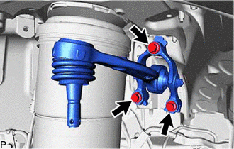
Remove the 3 bolts, front upper No. 2 arm bracket LH and front upper No. 2 suspension arm assembly LH.
-
- Click here
REMOVE FRONT UPPER NO. 1 SUSPENSION ARM ASSEMBLY LH (for 2WD)
-
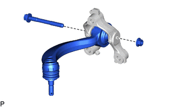
Remove the bolt, nut and front upper No. 1 suspension arm assembly LH from the front upper No. 1 arm bracket LH.
-
- Click here
REMOVE FRONT UPPER NO. 2 SUSPENSION ARM ASSEMBLY LH (for 2WD)
-
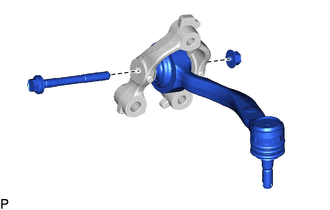
Remove the bolt, nut and front upper No. 2 suspension arm assembly LH from the front upper No. 2 arm bracket LH.
-
- Click here
REMOVE FRONT UPPER NO. 1 SUSPENSION ARM ASSEMBLY LH (for AWD)
-
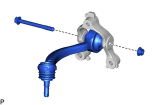
Remove the bolt, nut and front upper No. 1 suspension arm assembly LH from the front upper No. 1 arm bracket LH.
-
- Click here
REMOVE FRONT UPPER NO. 2 SUSPENSION ARM ASSEMBLY LH (for AWD)
-
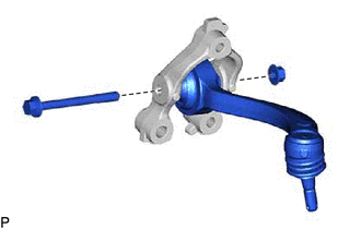
Remove the bolt, nut and front upper No. 2 suspension arm assembly LH from the front upper No. 2 arm bracket LH.
-