FRONT DOOR REASSEMBLY

CAUTION / NOTICE / HINT
Tech Tips
-
Use the same procedure for RHD and LHD vehicles.
-
The procedure listed below is for LHD vehicles.
-
Use the same procedure for the RH and LH sides.
-
The procedure listed below is for the LH side.
PROCEDURE
-
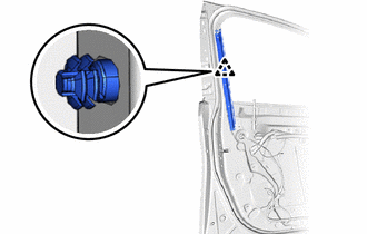
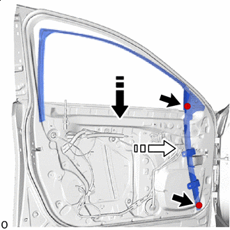
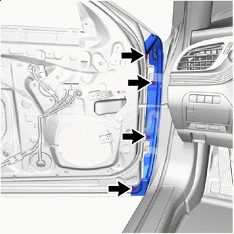
INSTALL FRONT DOOR WEATHERSTRIP LH
-
Degrease the front door weatherstrip LH installation surface using non-residue solvent.
-
Remove the peeling paper of the double-sided tape trying not to touch the adhesional surface.
-
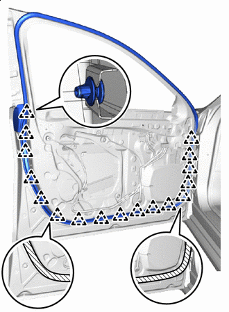

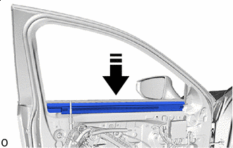
Double-sided Tape Attach the clip and install the new front door weatherstrip LH.
Note
Press the double-sided tape on the front door weatherstrip LH firmly to apply it.
-
-
INSTALL FRONT DOOR PANEL CUSHION
-
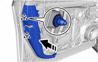
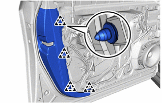
Attach the claw and install a new front door panel cushion.
-
-
INSTALL FRONT DOOR NO. 4 WEATHERSTRIP LH
-
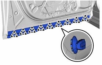
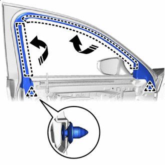
Attach the clip and install the front door No. 4 weatherstrip LH.
-
-
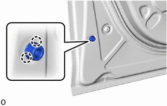
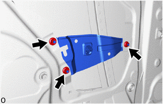
INSTALL FRONT DOOR CHECK ASSEMBLY LH
-
Clean the threaded portion on the vehicle body with non-residue solvent.
-
When reusing bolt:
-
Clean the threaded portion on the bolt with non-residue solvent.
-
Apply adhesive to the threads of the bolt.
Adhesive Toyota Genuine Adhesive 1324, Three Bond 1324 or equivalent.
-
-
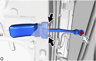

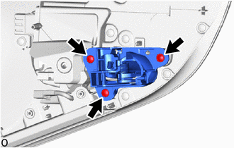
Nut 
Bolt Install the front door check assembly LH with the bolt and 2 nuts.
- Torque:
- Bolt
- 29 N*m { 296 kgf*cm, 21 ft.*lbf }
- Nut
- 8.0 N*m { 82 kgf*cm, 71 in.*lbf }
-
-
INSTALL FRONT DOOR INSIDE LOCKING CABLE ASSEMBLY LH
-
INSTALL FRONT DOOR LOCK REMOTE CONTROL CABLE ASSEMBLY LH
-
INSTALL FRONT DOOR LOCK COVER SUB-ASSEMBLY LH
-
INSTALL FRONT DOOR LOCK WITH MOTOR ASSEMBLY LH
-
INSTALL FRONT DOOR OUTSIDE HANDLE FRAME SUB-ASSEMBLY LH
-
Apply MP grease to the sliding parts of the front door outside handle frame sub-assembly LH.
-
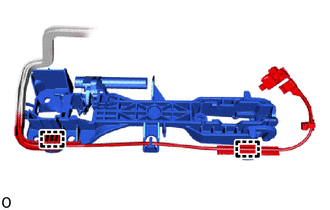
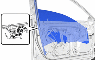
Attach the 2 wire harness clamps and guide.
-
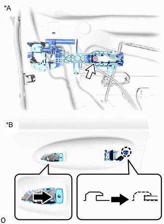
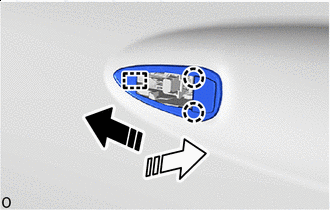
*A Outside *B Inside Attach the claw as shown in the illustration.
-
Using a T30 "TORX" socket wrench, install the front door outside handle frame sub-assembly LH with the TORX screw.
- Torque:
- 4.0 N*m { 41 kgf*cm, 35 in.*lbf }
-
-
INSTALL FRONT DOOR LOCK OPEN ROD LH
-
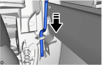

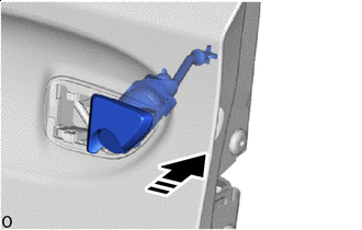
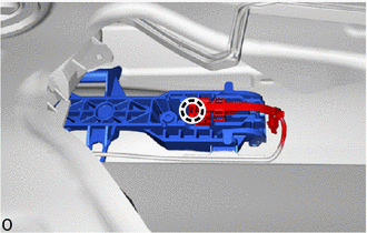
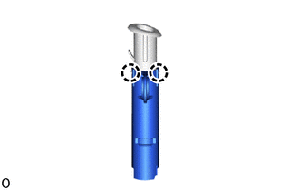
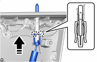
Install in this Direction Install the front door lock open rod LH on the front door lock with motor assembly LH as shown in the illustration.
Tech Tips
Check that the front door lock open rod LH is securely attached to the front door lock with motor assembly LH.
-
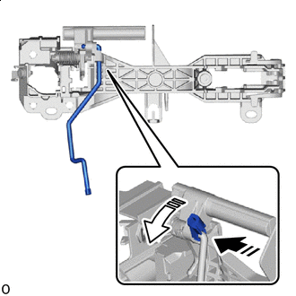
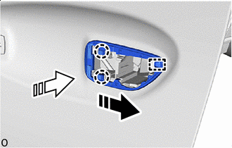
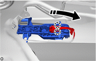
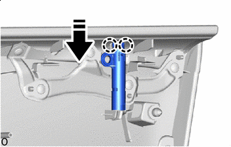
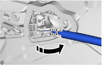
Install in this Direction (1) 
Install in this Direction (2) Install the front door lock open rod LH to the front door outside handle frame sub-assembly LH and attach the snap of the front door outside handle as shown in the illustration.
-
-
INSTALL FRONT DOOR FRONT OUTSIDE HANDLE PAD
-
Install in this Direction (1) Install in this Direction (2) Attach the guide in the direction indicated by the arrow shown in the illustration.
-
Attach the claw in the direction indicated by the arrow shown in the illustration to install the front door front outside handle pad.
-
-
INSTALL FRONT DOOR REAR OUTSIDE HANDLE PAD
-
Install in this Direction (1) Install in this Direction (2) Attach the guide in the direction indicated by the arrow shown in the illustration.
-
Attach the claw in the direction indicated by the arrow shown in the illustration to install the front door rear outside handle pad.
-
-
INSTALL FRONT DOOR LOCK CYLINDER ASSEMBLY LH (for Driver Side)
-
Apply MP grease to the sliding parts of the front door lock cylinder assembly LH.
-
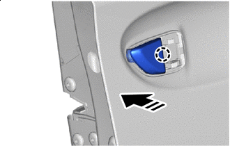
Install in this Direction Attach the guide for the front door lock cylinder assembly LH in the direction indicated by the arrow.
-
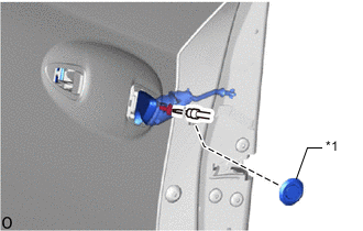
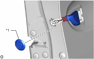
*1 Plug Hole Using a T30 "TORX" socket wrench, install the front door lock cylinder assembly LH with the TORX screw.
- Torque:
- 4.0 N*m { 41 kgf*cm, 35 in.*lbf }
-
Install the plug hole.
-
-
INSTALL FRONT DOOR OUTSIDE HANDLE COVER RH (for Front Passenger Side)
-
Install in this Direction Attach the claw of the front door outside handle cover RH in the direction indicated by the arrow.
-
*1 Plug Hole Using a T30 "TORX" socket wrench, install the front door outside handle cover RH with the TORX screw.
- Torque:
- 4.0 N*m { 41 kgf*cm, 35 in.*lbf }
-
Install the plug hole.
-
-
INSTALL FRONT DOOR OUTSIDE HANDLE ASSEMBLY LH
-
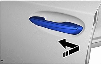
Install in this Direction Install the front door outside handle assembly LH in the direction of the arrow shown in the illustration.
-
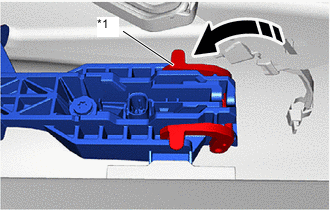
*1 Holder Install in this Direction Attach the holder as shown in the illustration.
-
Connect the connector.
-
Install in this Direction Attach the claw and close the connector cover as shown in the illustration.
-
-
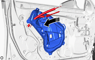
INSTALL FRONT DOOR WINDOW REGULATOR ASSEMBLY LH
-
Apply MP grease to the sliding parts of the front door window regulator assembly LH.
-
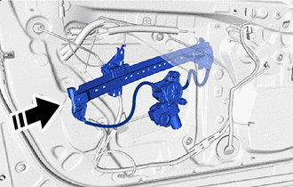
Install in this Direction Pull out the front door window regulator assembly LH from the service hole as shown in the illustration.
-
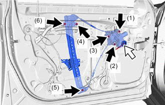
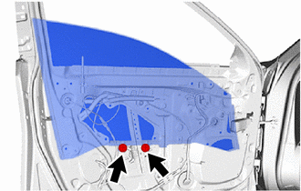
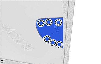
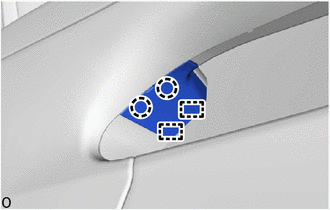
Nut Connector Install the front door window regulator assembly LH with the 6 nuts in the order shown in the illustration.
- Torque:
- 8.0 N*m { 82 kgf*cm, 71 in.*lbf }
Note
Do not damage the front door panel assembly with the front door window regulator assembly LH.
-
Connect the connector.
-
-
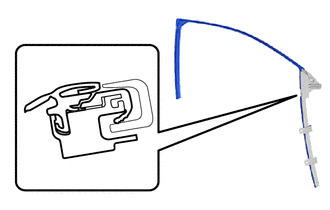
INSTALL FRONT DOOR REAR WINDOW FRAME LH
-
Attach the clip and install the front door rear window frame LH.
-
Install the nose piece to an air riveter and insert the mandrel section of a new φ 4 mm rivet into the nose piece.
-
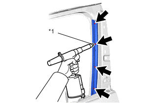
*1 Nose piece Press the rivets perpendicularly to the installation holes. Using the air riveter, install the front door rear window frame LH with the 4 rivets.
Note
Press the air riveter perpendicularly to the installation holes.
Tech Tips
Pull the trigger again to cut off the rivet if the rivet does not cut off.
-
-
INSTALL FRONT DOOR NO. 2 GLASS RUN LH
-
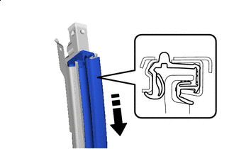
Install in this Direction Install the front door No. 2 glass run to the front door rear lower frame sub-assembly LH.
-
-
INSTALL FRONT DOOR REAR LOWER FRAME SUB-ASSEMBLY LH
-
Install in this Direction Attach the claw and install the front door rear lower frame sub-assembly LH to the front door rear window frame LH.
-
Install the bolt.
- Torque:
- 8.5 N*m { 87 kgf*cm, 75 in.*lbf }
-
-
INSTALL FRONT DOOR GLASS SUB-ASSEMBLY LH
-
Connect the 3 front multiplex network door ECU LH connectors.
-
Connect the connector and temporarily install the front door trim board sub-assembly LH.
-
Connect the cable to the negative (-) auxiliary battery terminal.
-
Turn the power switch on (IG).
-
Move the front door glass sub-assembly LH until the installation bolts can be seen.
-
Turn the power switch off.
-
Disconnect the cable from the negative (-) auxiliary battery terminal.
CAUTION:
-
After disconnecting the cable from the negative (-) auxiliary battery terminal, wait for at least 90 seconds to start the operation.
-
If the airbag deploys for any reason, it may cause a serious accident.
-
-
Disconnect the connector and remove the front door trim board sub-assembly LH.
-
Disconnect the 3 front multiplex network door ECU LH connectors.
-
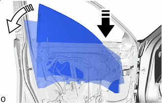
Install in this Direction (1) Install in this Direction (2) Temporarily install the front door glass sub-assembly LH to the front door window regulator assembly LH in the order shown in the illustration.
Note
Be careful not to damage the front door glass sub-assembly LH.
-
Install the front door glass sub-assembly LH with the 2 bolts.
- Torque:
- 8.0 N*m { 82 kgf*cm, 71 in.*lbf }
Note
Check that the frame portion on the rear side of the front door glass sub-assembly LH is installed in the groove of the front door No. 2 glass run.
-
-
INSTALL FRONT DOOR FRONT WINDOW FRAME MOULDING LH
-
INSTALL FRONT DOOR UPPER WINDOW FRAME MOULDING LH
-
INSTALL DOOR GUIDE PROTECTOR
-
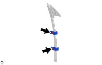
Install the 2 door guide protectors with the 2 clips.
-
-
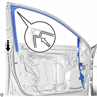
INSTALL FRONT DOOR FRONT GLASS RUN LH
-
Install the front door front glass run LH to the front pillar upper cover sub-assembly LH.
-
-
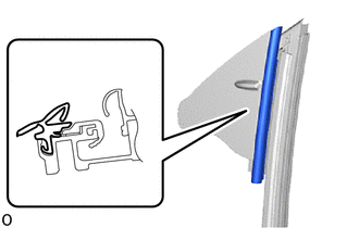
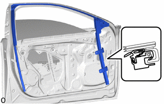
INSTALL FRONT DOOR GLASS RUN LH
-
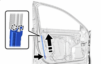
Install one part of the front door glass run LH to the front pillar upper cover sub-assembly LH as shown in the illustration.
-
-
INSTALL FRONT PILLAR UPPER COVER SUB-ASSEMBLY LH
-
Install in this Direction (1) Install in this Direction (2) Slide the front door glass run LH in the direction indicated by the arrow shown in the illustration and temporarily install it together with the front pillar upper cover sub-assembly LH with the 2 bolts.
Note
Check that the frame portion on the front side of the front door glass sub-assembly LH is attached to the front door glass run LH.
-
Install in this Direction (1) Install in this Direction (2) Install the front door glass run LH as shown in the illustration.
-
-
ADJUST FRONT DOOR GLASS SUB-ASSEMBLY LH
-
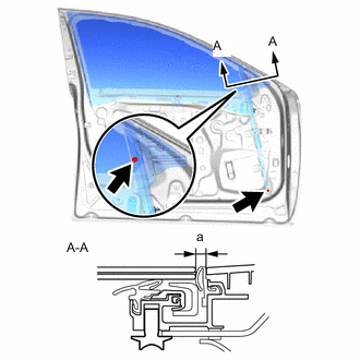
Tighten the front pillar upper cover sub-assembly LH with the 2 bolts so the front door glass sub-assembly LH is at the position shown in the illustration when it is raised.
- Torque:
- 7.5 N*m { 76 kgf*cm, 66 in.*lbf }
Standard Clearance Area Measurement a 3.0 to 5.4 mm (0.118 to 0.213 in.)
-
-
INSTALL FRONT DOOR WINDOW FRAME MOULDING LH(CENTER PILLAR SIDE)
-
INSTALL FRONT DOOR REAR BELT MOULDING END COVER LH
Tech Tips
When installing the front door rear belt moulding end cover LH, heat the front door panel and front door rear belt moulding end cover LH using a heat light.
Item Temperature Front Door Panel 40 to 60°C (104 to 140°F) Front Door Rear Belt Moulding End Cover LH 20 to 30°C (68 to 86°F) CAUTION:
-
Do not touch the heat light and heated parts.
-
Touching the heat light may result in burns.
-
Touching heated parts for a long time may result in burns.
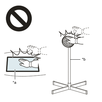
*a Heated Part *b Heat Light
-
Install a new front door rear belt moulding end cover LH.
-
Using a heat light, heat a new front door rear belt moulding end cover LH and the front door panel surface.
-
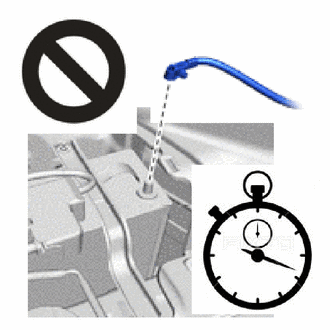
Remove the peeling paper from the face of the front door rear belt moulding end cover LH.
Tech Tips
After removing the peeling paper, keep the exposed adhesive free from foreign matter.
-
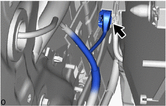
Double-sided Tape Attach the clip and install the front door rear belt moulding end cover LH as shown in the illustration.
Note
Press the double-sided tape on the front door rear belt moulding end cover LH firmly to apply it.
-
-
-
INSTALL FRONT DOOR BELT MOULDING LH
-
INSTALL FRONT DOOR NO. 2 WEATHERSTRIP LH
-
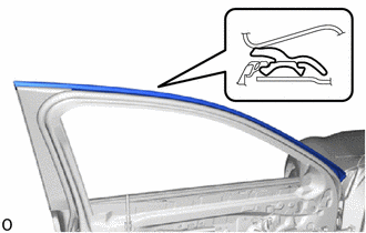
Align the No. 2 front door weatherstrip with the groove of the front door window frame front moulding LH and install it.
-
-
INSTALL FRONT DOOR NO. 3 WEATHERSTRIP LH
Tech Tips
When installing the front door No. 3 weatherstrip LH, heat the front door panel and front door No. 3 weatherstrip LH using a heat light.
Item Temperature Front Door Panel 40 to 60°C (104 to 140°F) Front Door No. 3 Weatherstrip LH 20 to 30°C (68 to 86°F) CAUTION:
-
Do not touch the heat light and heated parts.
-
Touching the heat light may result in burns.
-
Touching heated parts for a long time may result in burns.
*a Heated Part *b Heat Light
-
Install a new front door No. 3 weatherstrip LH.
-
Using a heat light, heat a new front door No. 3 weatherstrip LH and the front door panel surface.
-
Remove the peeling paper from the face of the front door No. 3 weatherstrip LH.
Tech Tips
After removing the peeling paper, keep the exposed adhesive free from foreign matter.
-
-
Double-sided Tape Attach the 4 clips and install the front door No. 3 weatherstrip LH.
Note
Press the double-sided tape on the front door No. 3 weatherstrip LH firmly to apply it.
-
-
INSTALL FRONT DOOR ARMREST SET BRACKET LH
-
Install the 2 screw grommets.
-
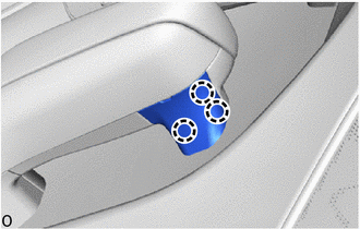
Install the front door armrest set bracket LH with the 3 nuts.
- Torque:
- 9.0 N*m { 92 kgf*cm, 80 in.*lbf }
-
-
INSTALL DOOR SIDE AIR BAG SENSOR LH
-
INSTALL OUTER REAR VIEW MIRROR ASSEMBLY LH
-
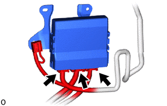
INSTALL FRONT MULTIPLEX NETWORK DOOR ECU LH
-
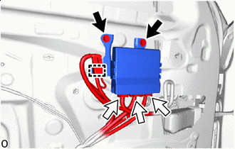
Screw Connector Install the front multiplex network door ECU LH with the 2 screws.
-
Connect the clamp and 3 connectors.
-
-
INSTALL OUTER MIRROR INSTALL HOLE COVER LH
-
INSTALL FRONT DOOR SERVICE HOLE COVER LH
-
Install in this Direction Pass the front door lock remote control cable assembly LH and front door inside locking cable assembly LH through the front door service hole cover LH.
-
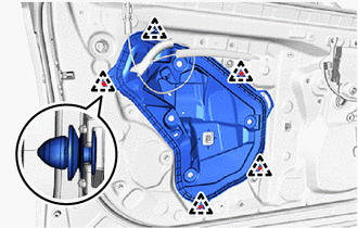
Attach the clip and install the front door service hole cover LH.
-
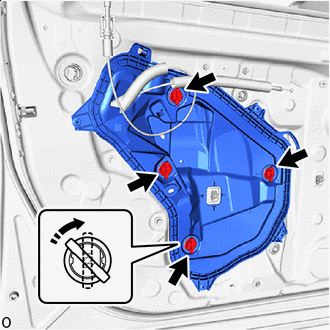
Turn Service Hole Cover Clip Turn the clips 45° in the direction indicated by the arrow shown in the illustration and install the 4 front door weatherstrip clips.
-
Connect the connector.
-
Connect the wire harness clamps.
-
-
INSTALL FRONT NO. 1 SPEAKER ASSEMBLY
-
INSTALL FRONT DOOR PANEL PROTECTOR LH
-
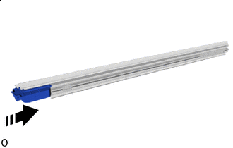
Install in this Direction Install the front door panel protector LH to the front door glass inner weatherstrip LH as shown in the illustration.
-
-
INSTALL FRONT DOOR VENT SEAL LH
-
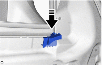
Install in this Direction Install the front door vent seal LH as shown in the illustration.
-
-
INSTALL FRONT DOOR GLASS INNER WEATHERSTRIP LH
-
Install in this Direction Install the front door glass inner weatherstrip LH in the direction indicated by the arrow shown in the illustration.
-
-
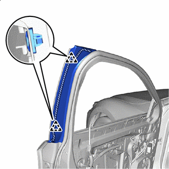
INSTALL UPPER DOOR FRAME GARNISH LH
-
Install in this Direction Attach the guide in the direction indicated by the arrow shown in the illustration and install the upper door frame garnish LH.
-
Attach the clip.
-
-
INSTALL FRONT DOOR TRIM COVER LH
-
Attach the 2 clips to the front door panel LH.
-
Install in this Direction Slide the front door trim cover LH in the direction indicated by the arrow shown in the illustration and attach the clip.
-
Attach the clip and install the front door trim cover LH.
-
-
INSTALL FRONT DOOR INSIDE HANDLE SUB-ASSEMBLY LH
-
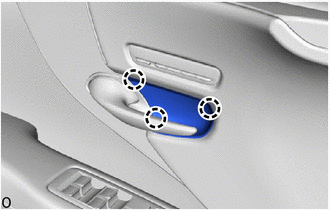
Install the front door inside handle sub-assembly LH with the 3 screws.
-
-
INSTALL SEAT MEMORY SWITCH LH
-
INSTALL NO. 2 SWITCH BEZEL
-
INSTALL FRONT DOOR INNER TRIM COVER LH
-
Attach the claw and install the front door inner trim cover LH.
-
-
INSTALL FRONT DOOR LOCK CONTROL KNOB HOLDER LH
-
Attach the claw and install the front door lock control knob holder LH to the door lock control knob bezel.
-
-
INSTALL DOOR LOCK CONTROL KNOB BEZEL LH
-
Install in this Direction Attach the claw and install the door lock control knob bezel LH together with the front door lock control knob holder LH.
-
-
INSTALL COURTESY LIGHT ASSEMBLY
-
INSTALL MULTIPLEX NETWORK MASTER SWITCH ASSEMBLY (for Driver Side)
-
INSTALL POWER WINDOW REGULATOR SWITCH ASSEMBLY (for Front Passenger Side)
-
INSTALL FRONT DOOR TRIM BOARD SUB-ASSEMBLY LH
-
Connect each connector.
-
Install in this Direction Attach the claw and connect the front door inside locking cable assembly LH.
-
Install in this Direction Connect the front door lock remote control cable assembly LH to the front door inside handle sub-assembly LH.
-
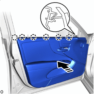
Install in this Direction Attach the claw in the direction indicated by the arrow shown in the illustration to install the front door trim board sub-assembly LH.
-
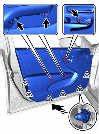
Install in this Direction Attach the clip and install the front door trim board sub-assembly LH.
-
Install the 3 screws.
-
-
INSTALL FRONT DOOR NO. 2 ARMREST COVER LH
-
Insert the guide, attach the claw and install the front door No. 2 armrest cover LH.
-
-
INSTALL FRONT DOOR ARMREST COVER LH
-
Attach the claw and install the front door armrest cover LH.
-
-
INSTALL FRONT DOOR TRIM UPPER COVER LH
-
Attach the claw and install the front door trim upper cover LH.
-
-
INSPECT FITTING OF FRONT DOOR
-
INSPECT FITTING OF FRONT DOOR TRIM BOARD SUB-ASSEMBLY
-
Remove the front door inner trim cover LH.
-
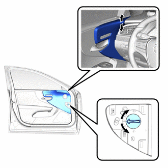
Rotate the dial to align the instrument panel safety pad sub-assembly stitching with the stitch line on the front door trim board sub-assembly LH as shown in the illustration.
Tech Tips
Adjust the front door trim board sub-assembly LH so that it is within the range of -2.0 to 2.0 mm (-0.079 to 0.079 in.).
-
Install the front door inner trim cover LH.
-
-
CONNECT CABLE TO NEGATIVE AUXILIARY BATTERY TERMINAL
Note
When disconnecting the cable, some systems need to be initialized after the cable is reconnected.
-
INSTALL LUGGAGE COMPARTMENT MAT SUB-ASSEMBLY
-
SRS WARNING LIGHT
-
PERFORM DIAGNOSTIC SYSTEM CHECK
-
INITIALIZE POWER WINDOW CONTROL SYSTEM
-
CHECK POWER WINDOW CONTROL SYSTEM
-
CHECK POWER DOOR LOCK CONTROL SYSTEM
-
INSPECT OUTER REAR VIEW MIRROR OPERATION
-
CHECK FRONT POWER SEAT CONTROL SYSTEM