| DTC Code | DTC Name |
|---|---|
| B2311 | Power Window Motor Malfunction |
DESCRIPTION
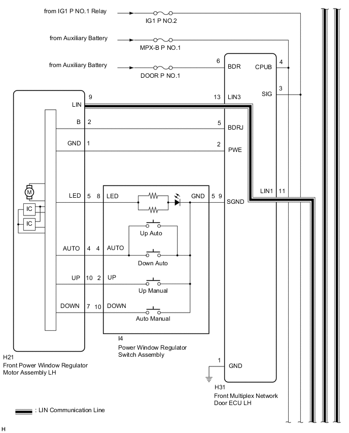
The power window regulator motor assemblies are operated by the multiplex network master switch assembly, power window regulator switch assembly or rear power window regulator switch assemblies. The power window regulator motor assemblies have motor, regulator and ECU functions.
This DTC is output when a power window regulator motor assembly is malfunctioning.
| DTC No. | Detection Item | DTC Detection Condition | Trouble Area |
|---|---|---|---|
| B2311 | Power Window Motor Malfunction | Front power window regulator motor assembly LH (for LHD) or front power window regulator motor assembly RH (for RHD) is malfunctioning |
|
| DTC No. | Detection Item | DTC Detection Condition | Trouble Area |
|---|---|---|---|
| B2311 | Power Window Motor Malfunction | Front power window regulator motor assembly RH (for LHD) or front power window regulator motor assembly LH (for RHD) is malfunctioning |
|
| DTC No. | Detection Item | DTC Detection Condition | Trouble Area |
|---|---|---|---|
| B2311 | Power Window Motor Malfunction | Rear power window regulator motor assembly LH is malfunctioning |
|
| DTC No. | Detection Item | DTC Detection Condition | Trouble Area |
|---|---|---|---|
| B2311 | Power Window Motor Malfunction | Rear power window regulator motor assembly RH is malfunctioning |
|
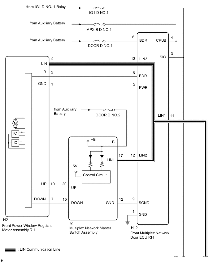
WIRING DIAGRAM
Click here
-

Table 5. *1 Instrument panel junction Block Assembly *2 Main Body ECU (Multiplex Network Body ECU) *3 LIN Communication Line 
for LHD:
-
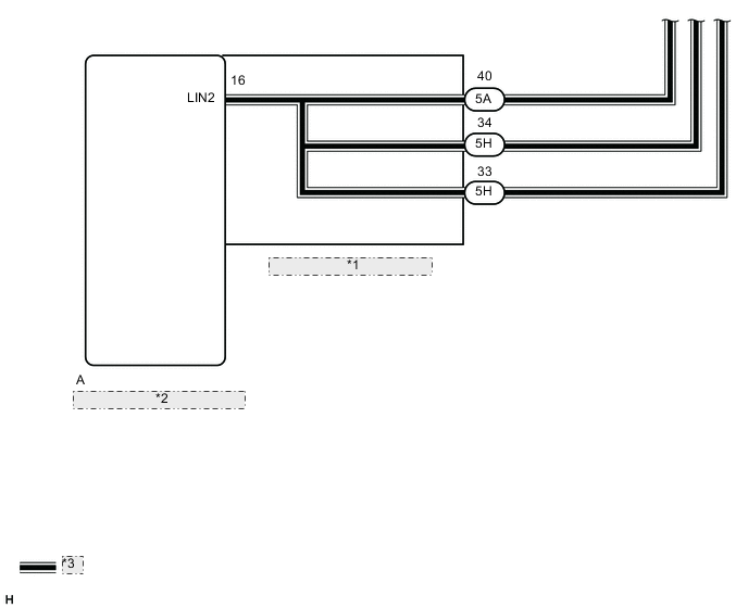
Table 6. *1 Instrument panel junction Block Assembly *2 Main Body ECU (Multiplex Network Body ECU) *3 LIN Communication Line 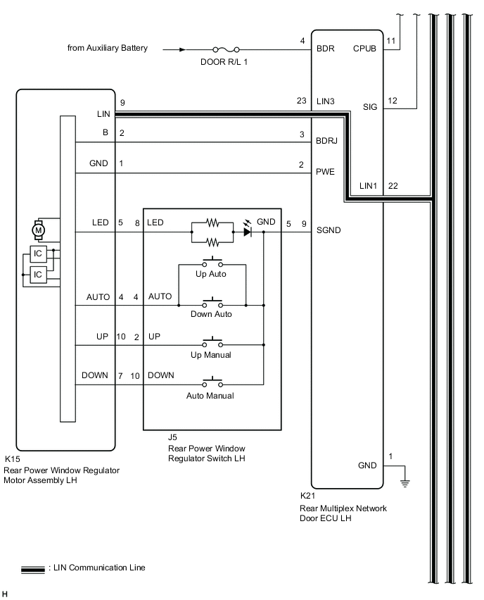
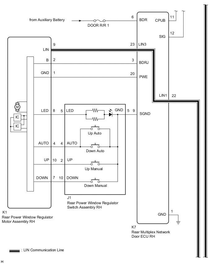
for RHD:
CAUTION / NOTICE / HINT
-
DTC B2311 is stored in each power window regulator motor assembly.
-
If a power window regulator motor assembly has been replaced with a new one, initialize the power window control system.
-
If a power window regulator motor assembly and door window regulator sub-assembly have been removed and installed, or if a power window regulator motor assembly was reused when a door glass or door glass run was replaced, initialize the power window control system.
-
Inspect the fuses for circuits related to this system before performing the following procedure.
-
The power window control system uses the LIN communication system. Inspect the communication function by following How to Proceed with Troubleshooting. Troubleshoot the power window control system after confirming that the communication system is functioning properly.
PROCEDURE
- Click here
CHECK FOR DTC
-
Clear the DTCs.
- Body Electrical > D-Door Motor > Clear DTCs
-
-
- Body Electrical > P-Door Motor > Clear DTCs
-
-
- Body Electrical > RL-Door Motor > Clear DTCs
-
-
- Body Electrical > RR-Door Motor > Clear DTCs
-
-
-
Check for DTCs.
- Body Electrical > D-Door Motor > Trouble Codes
-
-
- Body Electrical > P-Door Motor > Trouble Codes
-
-
- Body Electrical > RL-Door Motor > Trouble Codes
-
-
- Body Electrical > RR-Door Motor > Trouble Codes
-
-
Result Result Proceed to DTC B2311 is not output A DTC B2311 is output B
- A
USE SIMULATION METHOD TO CHECKClick here
- BClick here
-
- Click here
CHECK FOR DTC
-
Check the parts which the DTCs have been output from.
Result Result Proceed to DTC output from D-Door Motor (for LHD) A DTC output from D-Door Motor (for RHD) B DTC output from P-Door Motor (for LHD) C DTC output from P-Door Motor (for RHD) D DTC output from RL-Door Motor E DTC output from RR-Door Motor F
-
- Click here
CHECK HARNESS AND CONNECTOR (FRONT POWER WINDOW REGULATOR MOTOR ASSEMBLY LH - BATTERY AND BODY GROUND)
-

*a Component with harness connected
(Front Power Window Regulator Motor Assembly LH)
Measure the resistance according to the value(s) in the table below.
Standard Resistance Tester Connection Condition Specified Condition H21-1 (GND) - Body ground Always Below 1 Ω -
Measure the voltage according to the value(s) in the table below.
Standard Voltage Tester Connection Switch Condition Specified Condition H21-2 (B) - H21-1 (GND) Power switch off 11 to 14 V Result Proceed to OK NG
- OKClick here
GO TO STEP 9
- NG
REPAIR OR REPLACE HARNESS OR CONNECTOR
-
- Click here
CHECK HARNESS AND CONNECTOR (FRONT POWER WINDOW REGULATOR MOTOR ASSEMBLY RH - BATTERY AND BODY GROUND)
-
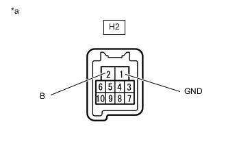
*a Component with harness connected
(Front Power Window Regulator Motor Assembly RH)
Measure the resistance according to the value(s) in the table below.
Standard Resistance Tester Connection Condition Specified Condition H2-1 (GND) - Body ground Always Below 1 Ω -
Measure the voltage according to the value(s) in the table below.
Standard Voltage Tester Connection Switch Condition Specified Condition H2-2 (B) - H2-1 (GND) Power switch off 11 to 14 V Result Proceed to OK NG
- OKClick here
GO TO STEP 9
- NG
REPAIR OR REPLACE HARNESS OR CONNECTOR
-
- Click here
CHECK HARNESS AND CONNECTOR (FRONT POWER WINDOW REGULATOR MOTOR ASSEMBLY RH - BATTERY AND BODY GROUND)
-
*a Component with harness connected
(Front Power Window Regulator Motor Assembly RH)
Measure the resistance according to the value(s) in the table below.
Standard Resistance Tester Connection Condition Specified Condition H21-1 (GND) - Body ground Always Below 1 Ω -
Measure the voltage according to the value(s) in the table below.
Standard Voltage Tester Connection Switch Condition Specified Condition H21-2 (B) - H21-1 (GND) Power switch off 11 to 14 V Result Proceed to OK NG
- OKClick here
GO TO STEP 9
- NG
REPAIR OR REPLACE HARNESS OR CONNECTOR
-
- Click here
CHECK HARNESS AND CONNECTOR (FRONT POWER WINDOW REGULATOR MOTOR ASSEMBLY LH - BATTERY AND BODY GROUND)
-
*a Component with harness connected
(Front Power Window Regulator Motor Assembly LH)
Measure the resistance according to the value(s) in the table below.
Standard Resistance Tester Connection Condition Specified Condition H2-1 (GND) - Body ground Always Below 1 Ω -
Measure the voltage according to the value(s) in the table below.
Standard Voltage Tester Connection Switch Condition Specified Condition H2-2 (B) - H2-1 (GND) Power switch off 11 to 14 V Result Proceed to OK NG
- OKClick here
GO TO STEP 9
- NG
REPAIR OR REPLACE HARNESS OR CONNECTOR
-
- Click here
CHECK HARNESS AND CONNECTOR (REAR POWER WINDOW REGULATOR MOTOR ASSEMBLY LH - BATTERY AND BODY GROUND)
-

*a Component with harness connected
(Rear Power Window Regulator Motor Assembly LH)
Measure the resistance according to the value(s) in the table below.
Standard Resistance Tester Connection Condition Specified Condition K15-1 (GND) - Body ground Always Below 1 Ω -
Measure the voltage according to the value(s) in the table below.
Standard Voltage Tester Connection Switch Condition Specified Condition K15-2 (B) - K15-1 (GND) Power switch off 11 to 14 V Result Proceed to OK NG
- OKClick here
GO TO STEP 9
- NG
REPAIR OR REPLACE HARNESS OR CONNECTOR
-
- Click here
CHECK HARNESS AND CONNECTOR (REAR POWER WINDOW REGULATOR MOTOR ASSEMBLY RH - BATTERY AND BODY GROUND)
-

*a Component with harness connected
(Rear Power Window Regulator Motor Assembly RH)
Measure the resistance according to the value(s) in the table below.
Standard Resistance Tester Connection Condition Specified Condition K1-1 (GND) - Body ground Always Below 1 Ω -
Measure the voltage according to the value(s) in the table below.
Standard Voltage Tester Connection Switch Condition Specified Condition K1-2 (B) - K1-1 (GND) Power switch off 11 to 14 V Result Proceed to OK NG
- OKClick here
- NG
REPAIR OR REPLACE HARNESS OR CONNECTOR
-
- Click here
PERFORM ACTIVE TEST USING GTS (APPLICABLE LOCATION)
-
Perform the Active Test according to the display on the GTS.
CAUTION:Be careful to avoid injuries as this test causes vehicle parts to move. During the Active Test, the jam protection function will not operate.
Tip:Up and down movement does not occur if the arrow is not pressed and held.
- Body Electrical > D-Door Motor > Active Test
Tester Display Measurement Item Control Range Diagnostic Note Power Window Power window OFF / DOWN / UP - -
-
- Body Electrical > P-Door Motor > Active Test
Tester Display Measurement Item Control Range Diagnostic Note Power Window Power window OFF / DOWN / UP - -
-
- Body Electrical > RL-Door Motor > Active Test
Tester Display Measurement Item Control Range Diagnostic Note Power Window Power window OFF / DOWN / UP - -
-
- Body Electrical > RR-Door Motor > Active Test
Tester Display Measurement Item Control Range Diagnostic Note Power Window Power window OFF / DOWN / UP - -
-
- Body Electrical > D-Door Motor > Active Test
Tester Display Power Window -
-
-
-
- Body Electrical > P-Door Motor > Active Test
Tester Display Power Window -
-
-
-
- Body Electrical > RL-Door Motor > Active Test
Tester Display Power Window -
-
-
-
- Body Electrical > RR-Door Motor > Active Test
Tester Display Power Window -
-
-
-
OK Each power window motor operates. Result Result Proceed to OK A NG (D-Door Motor) (for LHD) B NG (D-Door Motor) (for RHD) C NG (P-Door Motor) (for LHD) D NG (P-Door Motor) (for RHD) E NG (RL-Door Motor) F NG (RR-Door Motor) G - Body Electrical > D-Door Motor > Active Test
- AClick here
- B
REPLACE FRONT POWER WINDOW REGULATOR MOTOR ASSEMBLY LHClick here
- C
REPLACE FRONT POWER WINDOW REGULATOR MOTOR ASSEMBLY RHClick here
- D
REPLACE FRONT POWER WINDOW REGULATOR MOTOR ASSEMBLY RHClick here
- E
REPLACE FRONT POWER WINDOW REGULATOR MOTOR ASSEMBLY LHClick here
- F
REPLACE REAR POWER WINDOW REGULATOR MOTOR ASSEMBLY LHClick here
- G
REPLACE REAR POWER WINDOW REGULATOR MOTOR ASSEMBLY RHClick here
-
- Click here
PERFORM INITIALIZATION (APPLICABLE LOCATION)
-
Initialize the power window regulator motor assembly.
Tip:Initialize the power window regulator motor assembly that has DTC B2311 stored in its ECU.
Result Proceed to NEXT
- NEXTClick here
-
- Click here
CHECK POWER WINDOW CONTROL SYSTEM (APPLICABLE LOCATION)
-
Check that the power window operates normally by opening and closing the window.
Tip:Check the power window operation of the window for which DTC B2311 has been stored.
OK Each power window operates normally. Result Result Proceed to OK A NG (D-Door Motor) (for LHD) B NG (D-Door Motor) (for RHD) C NG (P-Door Motor) (for LHD) D NG (P-Door Motor) (for RHD) E NG (RL-Door Motor) F NG (RR-Door Motor) G
- AClick here
- B
REPLACE FRONT POWER WINDOW REGULATOR MOTOR ASSEMBLY LHClick here
- C
REPLACE FRONT POWER WINDOW REGULATOR MOTOR ASSEMBLY RHClick here
- D
REPLACE FRONT POWER WINDOW REGULATOR MOTOR ASSEMBLY RHClick here
- E
REPLACE FRONT POWER WINDOW REGULATOR MOTOR ASSEMBLY LHClick here
- F
REPLACE REAR POWER WINDOW REGULATOR MOTOR ASSEMBLY LHClick here
- G
REPLACE REAR POWER WINDOW REGULATOR MOTOR ASSEMBLY RHClick here
-
- Click here
CHECK WHETHER PARTS HAVE BEEN INSTALLED CORRECTLY
-
Check that the power window components are installed correctly.
OK Power window components are installed correctly. Result Proceed to OK NG
- OK
END (OVERHEATED POWER WINDOW REGULATOR MOTOR WAS DEFECTIVE)
- NG
INSTALL PARTS CORRECTLY
-