CAUTION / NOTICE / HINT
-
Use the same procedure for RHD and LHD vehicles.
-
The procedure listed below is for LHD vehicles.
PROCEDURE
- Click here
AIR SUSPENSION CONTROL PROHIBITED (w/ Air Suspension)
- Click here
REMOVE RADIATOR COVER PLATE
- Click here
REMOVE UPPER RADIATOR SUPPORT SEAL
- Click here
REMOVE LOWER RADIATOR AIR DEFLECTOR
- Click here
REMOVE OIL PAN PROTECTOR
-
for 2WD:
-
for AWD:
-
- Click here
RECOVER REFRIGERANT FROM REFRIGERATION SYSTEM
-
for HFC-134a(R134a):
-
for HFO-1234yf(R1234yf):
-
- Click here
DRAIN COOLANT (for Inverter)
- Click here
REMOVE POP UP HOOD LIFTER ASSEMBLY LH
- Click here
REMOVE HEADLIGHT ASSEMBLY RH
- Click here
REMOVE NO. 1 AIR CLEANER INLET
- Click here
REMOVE HOOD LOCK RELEASE LEVER PROTECTOR
-
Remove the 2 clips.
-
Detach the clamp and remove the hood lock release lever protector.
-
- Click here
REMOVE ENGINE HOOD COURTESY SWITCH (HOOD LOCK ASSEMBLY)
- Click here
REMOVE HIGH PITCHED HORN ASSEMBLY
- Click here
REMOVE LOW PITCHED HORN ASSEMBLY
- Click here
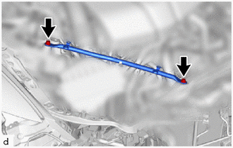
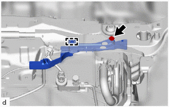
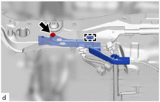
REMOVE LOWER ARM BRACKET BRACE SUB-ASSEMBLY RH
-
Remove the 2 bolts and lower arm bracket brace sub-assembly RH.
-
- Click here
REMOVE LOWER ARM BRACKET BRACE SUB-ASSEMBLY LH
-
Remove the 2 bolts and lower arm bracket brace sub-assembly LH.
-
- Click here
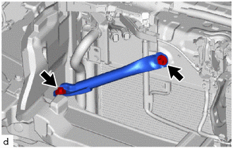
REMOVE RADIATOR SUPPORT TO CROSSMEMBER BRACE SUB-ASSEMBLY RH
-
Remove the 2 bolts and radiator support to crossmember brace sub-assembly RH.
-
- Click here
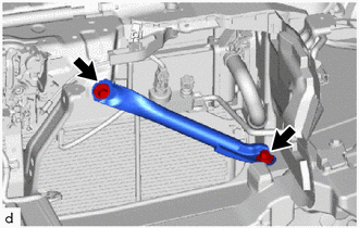
REMOVE RADIATOR SUPPORT TO CROSSMEMBER BRACE SUB-ASSEMBLY LH
-
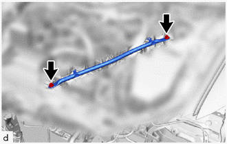
Remove the 2 bolts and radiator support to crossmember brace sub-assembly LH.
-
- Click here
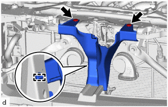
REMOVE UPPER RADIATOR SUPPORT SUB-ASSEMBLY
-
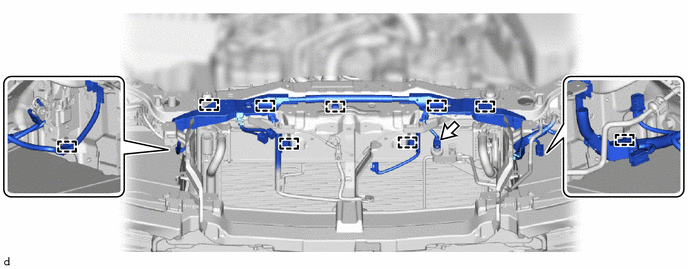
Disconnect the connector.
-
Detach the clamp and disconnect the engine room main wire.
-
for LHD:
-
Remove the screw.
-
Detach the clamp and disconnect the hood lock control cover LH.
-
-
Remove the screw.
-
Detach the clamp and disconnect the hood lock control cover RH.
-
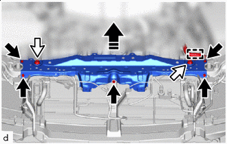

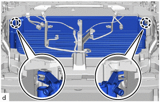
Bolt 
Sub-Radiator Support Cushion 
Remove in this Direction detach the clamp.
-
Remove the 5 bolts.
-
While lifting the upper radiator support sub-assembly upwards, detach the 2 sub-radiator support cushions and remove the upper radiator support sub-assembly.
Note:When disconnecting the upper radiator support sub-assembly, do not damage the cooler condenser assembly, radiator assembly (for inverter coolant) and radiator assembly.
-
- Click here
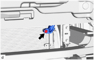
DISCONNECT NO. 2 INVERTER COOLING HOSE
-
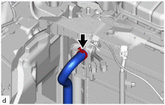
Using pliers, grip the claws of the hose clip and slide the hose clip to disconnect the No. 2 inverter cooling hose.
Note:
-
Do not apply excessive force to the radiator assembly (for inverter coolant) or No. 2 inverter cooling hose.
-
Prepare a drain pan or cloth in case the coolant leaks.
-
-
- Click here
DISCONNECT NO. 3 INVERTER COOLING HOSE
-
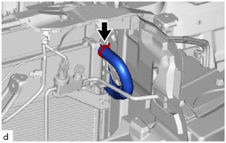
Using pliers, grip the claws of the hose clip and slide the hose clip to disconnect the No. 3 inverter cooling hose.
Note:
-
Do not apply excessive force to the radiator assembly (for inverter coolant) or No. 3 inverter cooling hose.
-
Prepare a drain pan or cloth in case the coolant leaks.
-
-
- Click here
DISCONNECT LIQUID TUBE SUB-ASSEMBLY A
-
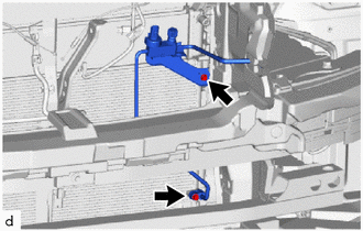
Remove the 2 bolts and disconnect liquid tube sub-assembly A and No. 1 cooler bracket from the cooler condenser assembly.
Note:Do not apply excessive force to the liquid tube sub-assembly A.
-
Remove the O-ring from the liquid tube sub-assembly A.
Note:Seal the openings of the disconnected parts using vinyl tape to prevent entry of moisture and foreign matter.
-
- Click here
DISCONNECT DISCHARGE HOSE SUB-ASSEMBLY
-
Remove the bolt and disconnect the discharge hose sub-assembly from the cooler condenser assembly.
Note:Do not apply excessive force to the discharge hose sub-assembly.
-
Remove the O-ring from the discharge hose sub-assembly.
Note:Seal the openings of the disconnected parts using vinyl tape to prevent entry of moisture and foreign matter.
-
- Click here
REMOVE COOLER CONDENSER ASSEMBLY
-
Detach the claw.
-
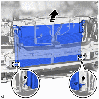
Remove in this Direction While lifting the cooler condenser assembly in the direction of the arrow shown in the illustration, detach the guide and remove the cooler condenser assembly and radiator assembly (for inverter coolant).
Note:
-
When removing the cooler condenser assembly and radiator assembly (for inverter coolant), do not damage the cooler condenser assembly, radiator assembly (for inverter coolant) and radiator assembly.
-
Prepare a drain pan or cloth in case the coolant leaks.
-
-
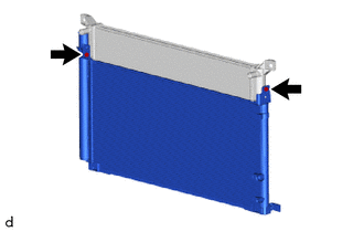
Remove the 2 bolts and the radiator assembly (for inverter coolant) from the cooler condenser assembly.
-